SMD Diode Selection Guide: Technical Parameters, Applications, and Design Considerations
Table of Contents
- Introduction: Why SMD Diode Selection Matters
- Key Technical Parameters of SMD Diodes
- SMD Diode Types and Their Applications
- How to Choose the Right SMD Diode for Your Design
- PCB Layout and Thermal Management Best Practices
- Supply Chain Considerations and Sourcing Strategy
- FAQ
- Conclusion: SMD Diode Selection Checklist
1. Introduction: Why SMD Diode Selection Matters
SMD diodes (surface mount diodes) are fundamental semiconductor components in modern electronic designs, serving critical functions from power rectification and voltage regulation to circuit protection and signal processing. Unlike through-hole diodes, SMD diodes offer significant advantages in PCB real estate savings, automated assembly compatibility, and improved high-frequency performance due to reduced parasitic inductance.
However, selecting the wrong SMD diode can lead to thermal failures, inadequate surge protection, or unexpected voltage drops that compromise system reliability. In automotive applications, a poorly chosen Zener diode might fail AEC-Q101 qualification. In high-frequency switching power supplies, using a standard rectifier instead of a Schottky diode can reduce efficiency by 3-5%. In cost-sensitive consumer electronics, overlooking package thermal resistance can necessitate expensive thermal management solutions.
This guide provides practical selection methodology based on real-world design experience. You'll learn how to interpret datasheet parameters, match diode characteristics to application requirements, avoid common layout mistakes, and navigate supply chain challenges. Whether you're designing a buck converter for industrial automation, protecting automotive CAN bus interfaces, or selecting ESD protection for USB ports, this guide helps you make informed decisions that balance performance, cost, and reliability.
2. Key Technical Parameters of SMD Diodes
Understanding datasheet parameters is essential for proper SMD diode selection. Here are the critical specifications that directly impact circuit performance and reliability.
Forward Voltage Drop (VF)
Forward voltage drop is the voltage across the diode when conducting current. For rectifier diodes, VF typically ranges from 0.7V to 1.2V at rated current. Schottky diodes offer lower VF (0.3V to 0.5V), making them ideal for low-voltage, high-efficiency applications. In a 5V power supply, switching from a standard diode (VF = 0.7V) to a Schottky (VF = 0.4V) improves efficiency by approximately 6%.
However, VF increases with temperature and current. Always check the VF curve in the datasheet across your operating temperature range. A diode with VF = 0.4V at 25°C might reach 0.5V at 85°C, affecting dropout voltage calculations in linear regulators.
Reverse Breakdown Voltage (VBR or VRRM)
This parameter defines the maximum reverse voltage the diode can withstand before avalanche breakdown occurs. For safety, select a diode with VBR at least 20% higher than the maximum reverse voltage in your circuit. In automotive 12V systems with load dump transients reaching 40V, use diodes rated for at least 50V. For mains-connected rectifiers in 230VAC systems, 600V or 1000V ratings are standard.
Maximum Forward Current (IF)
IF specifies the continuous forward current the diode can handle without exceeding its junction temperature limit. This parameter is typically given at 25°C ambient with specific PCB copper area for heat dissipation. In practice, derate IF by 50% for designs operating at 70°C ambient or with limited cooling.
Peak non-repetitive forward current (IFSM) is equally important for applications with high inrush currents, such as input rectifiers in switching power supplies. IFSM ratings are typically 10-30 times higher than IF but only for 8.3ms (half-cycle at 60Hz).
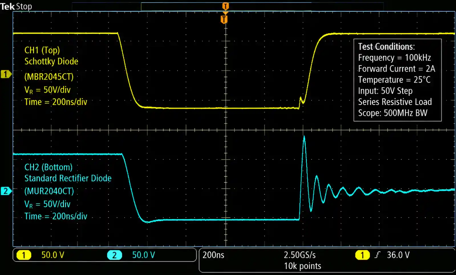
Reverse Recovery Time (trr)
Reverse recovery time is critical in high-frequency switching applications. When a diode transitions from forward conduction to reverse blocking, minority carriers must be swept out, causing a brief reverse current spike. Standard rectifier diodes have trr of 1-3µs, which is unacceptable for switching frequencies above 20kHz. Fast recovery diodes offer trr below 500ns, while Schottky diodes provide near-zero trr due to their majority-carrier operation.
In a 100kHz buck converter, using a standard diode as the freewheeling diode can cause 15-20% efficiency loss and significant EMI issues due to reverse recovery transients.
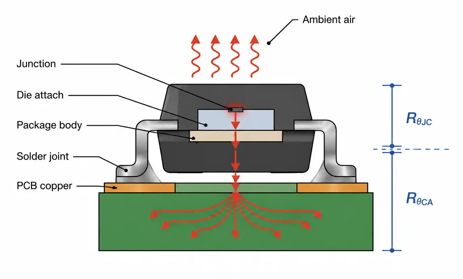
Thermal Resistance (RθJA and RθJC)
Thermal resistance determines how much the junction temperature rises above ambient for each watt of power dissipation. RθJA (junction-to-ambient) depends heavily on PCB copper area and typically ranges from 50°C/W to 150°C/W for small SMD packages like SOD-323. RθJC (junction-to-case) is a more consistent parameter for designs with defined thermal management.
Junction temperature (TJ) must stay below the rated maximum (typically 125°C to 150°C). Calculate TJ using: TJ = TA + (VF × IF × RθJA). A diode dissipating 0.5W with RθJA = 100°C/W will see a 50°C temperature rise.
3. SMD Diode Types and Their Applications
Different SMD diode technologies offer distinct advantages for specific applications. Understanding these trade-offs is essential for optimal component selection.
Schottky Barrier Diodes
Schottky diodes use a metal-semiconductor junction instead of a P-N junction, resulting in lower forward voltage drop (0.3V-0.5V) and near-zero reverse recovery time. These characteristics make them ideal for high-efficiency power conversion, particularly in low-voltage applications where minimizing conduction losses is critical.
Common applications include synchronous rectification in buck converters, output rectifiers in flyback converters below 100V, reverse polarity protection in battery-powered devices, and freewheeling diodes in motor drives. However, Schottky diodes have higher reverse leakage current (10-100µA) compared to standard diodes (1-10µA), which can be problematic in ultra-low-power designs. Their reverse voltage ratings are typically limited to 200V, with most cost-effective options below 100V.
Fast Recovery and Ultra-Fast Recovery Diodes
Fast recovery diodes bridge the gap between standard rectifiers and Schottky diodes, offering trr from 35ns to 500ns with reverse voltage ratings up to 1200V. They're essential for high-voltage switching applications where Schottky diodes cannot provide adequate breakdown voltage.
Use fast recovery diodes in PFC (power factor correction) boost converters operating at 50-100kHz, high-voltage flyback converters, snubber circuits in IGBT drives, and inverter output rectification. The key selection criterion is matching trr to switching frequency—at 100kHz switching, select diodes with trr below 200ns to minimize recovery losses.
Zener Diodes
Zener diodes are designed to operate in reverse breakdown mode, providing voltage regulation and overvoltage protection. SMD Zener diodes are available in voltage ratings from 2.4V to 200V with power ratings typically from 200mW to 5W depending on package size.
Critical applications include voltage reference generation in analog circuits, transient voltage suppression for automotive and industrial interfaces, gate protection in MOSFETs, and voltage clamping in signal processing circuits. When selecting Zener diodes, pay attention to the voltage tolerance (typically ±5%), which affects regulation accuracy, and the Zener impedance, which determines dynamic regulation performance under varying load currents.
TVS (Transient Voltage Suppressor) Diodes
TVS diodes are specialized Zener diodes optimized for high-energy transient absorption. They feature extremely low clamping voltage and response time below 1ps, making them superior to standard Zeners for ESD and surge protection.
Deploy TVS diodes for IEC 61000-4-2 ESD protection on USB, HDMI, and other interface ports, automotive surge protection per ISO 7637-2, lightning surge protection in industrial equipment, and load dump protection in automotive electronics. Unidirectional TVS diodes protect DC lines, while bidirectional types are used for AC or bidirectional signal lines.
| Diode Type | Forward Voltage | Reverse Recovery | Voltage Rating | Primary Applications |
|---|---|---|---|---|
| Schottky | 0.3V - 0.5V | <10ns | Up to 200V | Low-voltage SMPS, polarity protection, high-frequency rectification |
| Fast Recovery | 0.7V - 1.0V | 35ns - 500ns | Up to 1200V | PFC circuits, high-voltage SMPS, inverter rectification |
| Ultra-Fast Recovery | 0.7V - 1.0V | <35ns | Up to 600V | High-frequency inverters, resonant converters, induction heating |
| Standard Rectifier | 0.7V - 1.2V | 1µs - 3µs | Up to 1000V | 50/60Hz rectification, low-frequency applications, DC blocking |
| Zener | N/A | N/A | 2.4V - 200V | Voltage regulation, reference generation, overvoltage clamping |
| TVS | N/A | <1ps response | 5V - 600V | ESD protection, surge suppression, transient absorption |
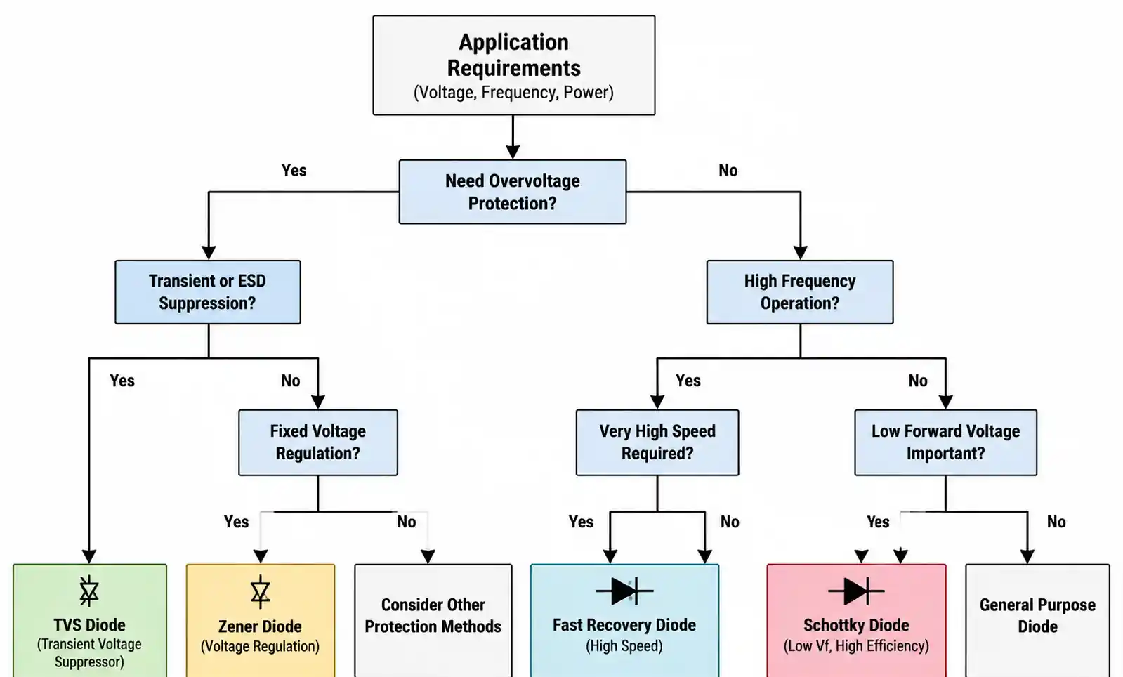
This comparison table helps narrow your selection based on your circuit's voltage, frequency, and protection requirements. For instance, if you're designing a 24V buck converter operating at 200kHz, a Schottky diode is the clear choice for the freewheeling position. For a 400V PFC stage at 65kHz, select a fast recovery diode with trr below 150ns.
4. How to Choose the Right SMD Diode for Your Design
Proper SMD diode selection requires systematic evaluation of electrical requirements, thermal constraints, and reliability criteria. Here's a proven methodology used in production designs.
Step 1: Define Electrical Requirements
Start by determining the fundamental electrical parameters from your circuit analysis. Calculate maximum forward current including transient conditions—for input rectifiers, account for capacitor charging inrush current which can be 10-20 times steady-state current for the first few milliseconds. Identify peak reverse voltage including worst-case transients and safety margins. In automotive designs, this means considering load dump (up to +100V) and reverse battery (-14V).
Determine operating frequency and required switching speed. Any application above 20kHz switching frequency eliminates standard rectifiers. Above 100kHz, Schottky diodes or ultra-fast recovery diodes become necessary unless you accept significant efficiency penalties.
Step 2: Calculate Power Dissipation and Thermal Requirements
Power dissipation in conducting diodes is primarily determined by forward voltage drop: P = VF × IF(avg). For rectifiers with pulsed current, use RMS current rather than average current for thermal calculations. In a full-bridge rectifier supplying 2A DC with 1.0V forward drop per diode, each diode dissipates approximately 1W (considering conduction duty cycle).
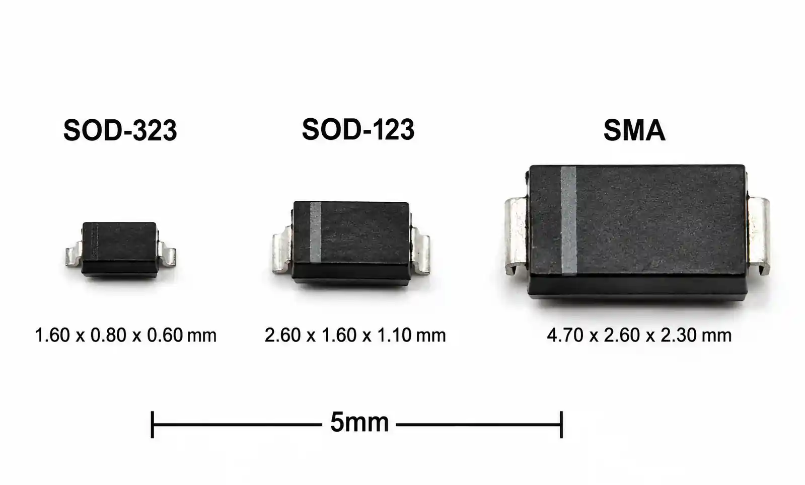
Next, calculate required thermal resistance. If your maximum ambient temperature is 70°C, maximum junction temperature is 125°C, and power dissipation is 0.8W, you need RθJA < (125-70)/0.8 = 69°C/W. This calculation often determines the minimum package size—a SOD-323 package with RθJA of 150°C/W would be inadequate, requiring an SOD-123 or larger.
Step 3: Select Package Type Based on Power and Assembly
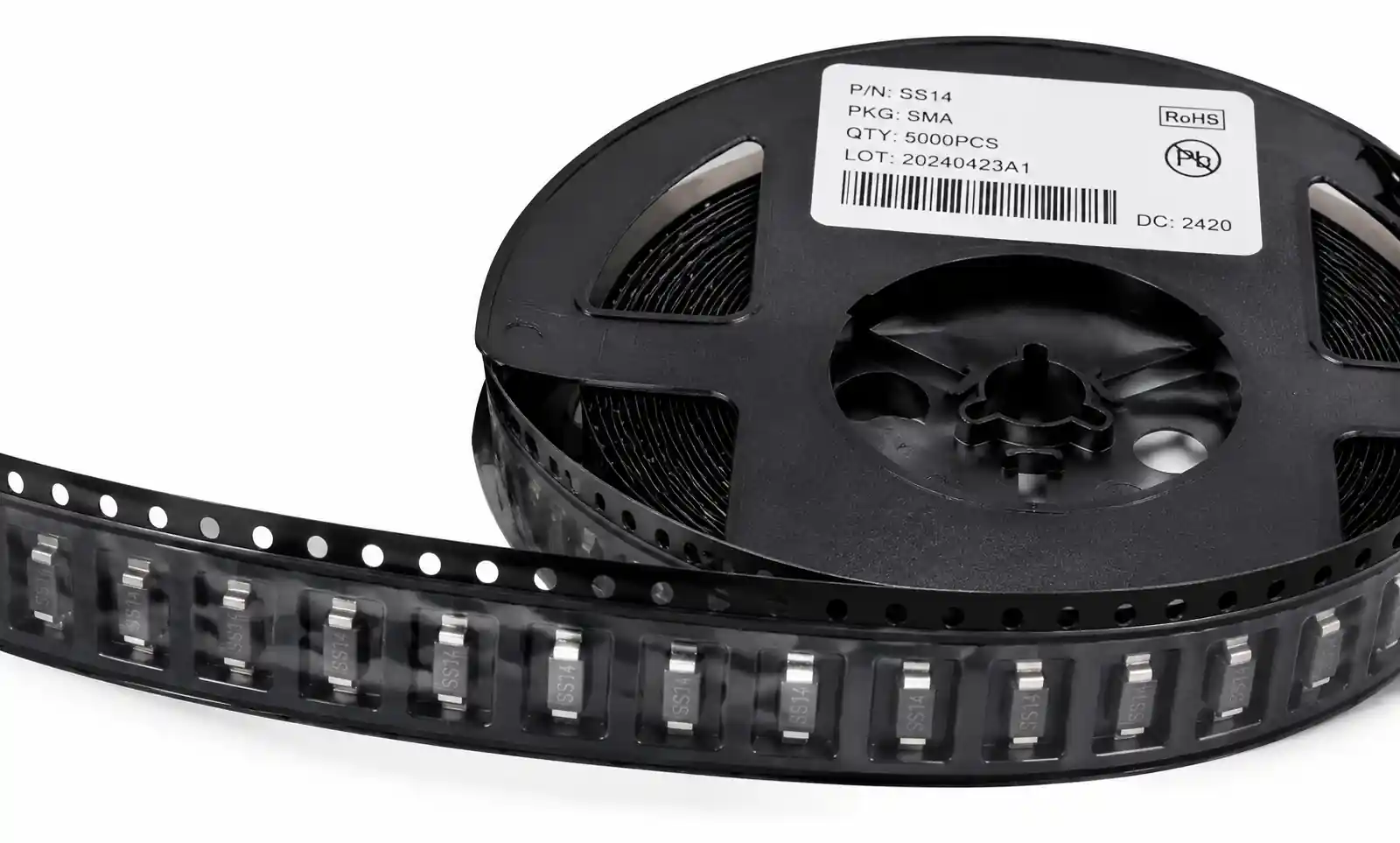
SMD diode packages range from tiny SOD-323 (1.25mm × 1.6mm) to larger SMA (2.6mm × 4.5mm) and SMB/SMC packages for higher power. Package selection balances thermal performance, board space, and manufacturing considerations.
For signal diodes and low-power applications (<250mW), SOD-323 or SOD-523 packages are suitable. For power rectification up to 1A and moderate power dissipation (<1W with adequate copper area), SOD-123 is commonly used. For higher power applications (1-3A), select SMA, DO-214AC, or SOD-123FL packages. Beyond 3A, consider SMB (DO-214AA) or SMC (DO-214AB) packages, or transition to through-hole solutions if thermal management becomes challenging.
Step 4: Consider Application-Specific Requirements
Automotive applications require AEC-Q101 qualification, extended temperature range (-40°C to +150°C junction), and consideration of specific failure modes per ISO 26262. Medical devices may require UL 60601 recognition. Consumer electronics prioritize cost-effectiveness and compact size.
For high-reliability applications, review MTBF data and failure rate specifications. Understand whether your application permits graceful degradation (open-circuit failure mode) or requires fail-safe design (redundant protection paths).
Step 5: Evaluate Supply Chain and Cost
Check component availability and lead times from major distributors. Parts with single-source suppliers or limited fab capacity present risk in high-volume production. Identify pin-compatible alternatives from multiple manufacturers.
Perform cost-volume analysis including quantity breaks. A component that costs $0.05 at 10K units might drop to $0.025 at 100K units, significantly impacting BOM cost in high-volume consumer products.
| Selection Criteria | Consumer Electronics | Industrial Equipment | Automotive Systems |
|---|---|---|---|
| Temperature Range | 0°C to +70°C | -20°C to +85°C | -40°C to +125°C (TJ up to 150°C) |
| Qualification | CE, RoHS | CE, UL, IEC | AEC-Q101, IATF 16949 |
| MTBF Target | 20,000 - 50,000 hrs | 50,000 - 100,000 hrs | 100,000+ hrs |
| Cost Sensitivity | Very high (cents matter) | Moderate | Lower (reliability priority) |
| Key Failure Mode | Early life failures acceptable | Field failures costly | Zero-defect mentality |
| Typical Lead Time | 8-12 weeks | 12-16 weeks | 16-24 weeks (qualified parts) |
Understanding these application-specific priorities helps avoid over-engineering (adding unnecessary cost) or under-engineering (causing field failures). An automotive power supply justifies the cost of AEC-Q101 parts and extensive testing, while a consumer USB charger requires aggressive cost optimization.
5. PCB Layout and Thermal Management Best Practices
Proper PCB layout is crucial for SMD diode performance and reliability. Poor layout can cause thermal failures, EMI issues, and premature component degradation even with correctly specified parts.
Copper Area for Thermal Management
SMD diode thermal performance depends heavily on PCB copper area acting as a heatsink. Datasheet thermal resistance values typically assume specific copper areas—commonly 1 square inch (645mm²) of 2oz copper. Reducing copper area to 0.5 square inch can increase thermal resistance by 40-60%.
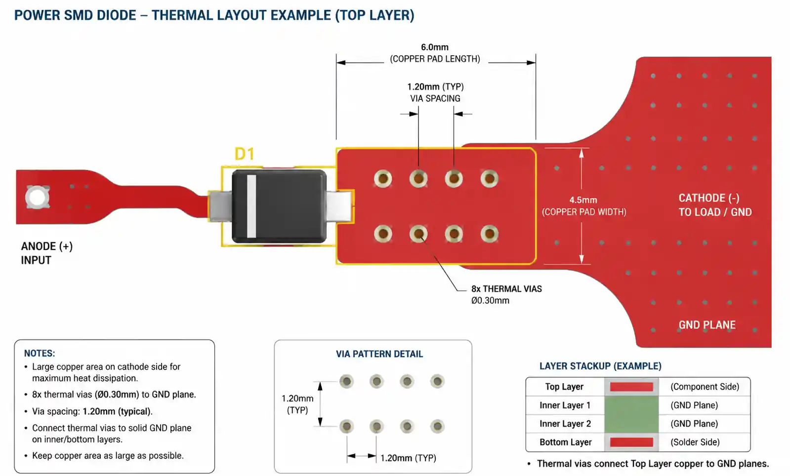
For power diodes dissipating more than 0.5W, dedicate at least 1 square inch of 2oz copper connected to the cathode pad (typically the higher power connection). Use thermal vias to connect top-layer copper to inner ground planes—4 to 8 vias of 0.3mm diameter provide effective heat transfer. Space vias 1-2mm from the component pad to avoid solder wicking during reflow.
In multilayer boards, distribute copper on multiple layers. A four-layer board with 2oz copper on outer layers and 1oz on inner layers can reduce thermal resistance by 30-40% compared to a two-layer design.
High-Frequency Layout Considerations
In switching power supplies, diode placement and trace routing directly impact efficiency and EMI. Place the freewheeling diode as close as possible to the inductor connection point—every millimeter of trace adds parasitic inductance that increases voltage ringing and switching losses.
Minimize the loop area formed by the switching transistor, freewheeling diode, and input capacitor. This high di/dt loop is the primary EMI source in switching converters. In a buck converter, place the input capacitor, switching FET, and freewheeling diode in a tight triangular arrangement with total loop area below 100mm².
Use ground planes extensively for low-impedance return paths. Do not route high-frequency switching currents through narrow ground traces, as this creates common-mode noise coupling to sensitive analog circuits.
Protection Against Thermal and Electrical Stress
Implement thermal relief for SMD diodes in high-stress applications. While solid copper provides maximum heat dissipation, it also increases thermal stress during soldering. For production yield optimization, use 2-3 thermal relief spokes (0.3-0.5mm width) connecting the pad to larger copper areas.
For diodes in exposed positions susceptible to ESD or voltage transients, add series resistance (1-10Ω) when possible to limit peak fault current. In TVS diode applications, this resistance is intentional—it allows the TVS to clamp voltage before fault current exceeds rating.
Keep high-voltage traces at least 0.5mm away from adjacent conductors for every 100V of potential difference. For 400V rectifiers, maintain 2mm spacing. Follow IPC-2221 creepage and clearance requirements for your voltage and pollution degree.
6. Supply Chain Considerations and Sourcing Strategy
Component availability and supply chain resilience are increasingly critical in SMD diode selection. A technically perfect design is worthless if parts become unobtainable during production ramp.
Multi-Source Strategy
Identify pin-compatible alternatives from multiple manufacturers during the design phase, not when your primary source goes on allocation. For instance, if you select a Schottky diode in SOD-323 package with 40V rating and 0.4V forward drop, qualify alternatives from at least two additional manufacturers with equivalent electrical and package specifications.
Create a qualification matrix comparing key parameters across alternatives. Small differences in VF (±0.05V) or trr (±20ns) usually don't impact design, but verify this through testing. Maintain approved vendor lists (AVL) with at least three qualified sources for high-volume products.
Lead Time Management
Standard SMD diodes from major manufacturers typically have 8-16 week lead times for production quantities. Specialty parts (high-voltage TVS, high-current Schottky in specific packages) can extend to 20-26 weeks. Automotive-qualified parts often require 24-30 weeks for initial orders.
Implement rolling forecasts with your distributors to secure allocation during tight supply conditions. Many distributors offer vendor-managed inventory (VMI) programs that guarantee supply for committed volumes. These programs typically require 6-12 month commitments but provide pricing stability and allocation protection.
Obsolescence Risk Management
Check product lifecycle status before committing to a design. Components marked "not recommended for new designs" or in "last-time-buy" status present obvious risks. However, even active parts can become unavailable—a fab consolidation, process change, or business divestiture can strand your design.
Favor components with broad industry adoption and multiple second-sources. A generic 1N4148 signal diode in SOD-323 has dozens of qualified manufacturers and minimal obsolescence risk. A proprietary high-voltage Schottky from a single supplier presents much higher risk.
Review component roadmaps with manufacturer representatives for critical designs. Many suppliers provide 3-5 year commitment letters for strategic customers, guaranteeing continued production and providing advance notice of any discontinuation.
Cost Optimization
SMD diode pricing varies dramatically with volume, package, and specifications. At 100-unit quantities, most small-signal diodes cost $0.02-0.10. At 10,000 units, prices drop to $0.005-0.03. At 100,000+ units, commodity parts can reach $0.002-0.01.
High-voltage, fast-recovery, and automotive-qualified parts command premium pricing—typically 2-5× standard parts. Evaluate whether your application truly requires these specifications or if you're over-engineering. A 600V ultra-fast diode might cost $0.15 while a 400V fast-recovery alternative costs $0.05—if your maximum voltage is 300V, the lower-rated part provides adequate safety margin at one-third the cost.
Consider packaging format impact on cost. Tape-and-reel packaging is essential for automated assembly but adds handling cost. For prototypes and low-volume production (<1000 units), cut tape can reduce cost by 15-30%. For high-volume production, negotiate reel quantities that match your production run sizes to minimize waste.
| Supply Chain Factor | Risk Mitigation Strategy | Implementation Timeline |
|---|---|---|
| Single-source dependency | Qualify 2-3 alternatives with compatible specifications | During design phase |
| Long lead times (>16 weeks) | Establish VMI agreements or maintain safety stock | 6 months before production |
| Price volatility | Lock multi-year pricing for high-volume designs | During supplier negotiations |
| Obsolescence | Monitor product lifecycle, establish alternative qualification process | Ongoing, review quarterly |
| Allocation during shortage | Develop strategic relationships, commit to forecasts | Ongoing relationship management |
| Counterfeit risk | Source from authorized distributors, implement incoming inspection | Procurement policy |
Supply chain resilience requires proactive management. Waiting until you encounter allocation issues or price increases creates crisis situations that compromise design decisions and production schedules.
7. FAQ
What is the difference between Schottky diodes and standard rectifier diodes?
Schottky diodes use a metal-semiconductor junction, resulting in lower forward voltage drop (0.3-0.5V vs 0.7-1.2V) and negligible reverse recovery time (<10ns). This makes them significantly more efficient in low-voltage, high-frequency applications like switching power supplies. However, they have higher reverse leakage current and lower maximum reverse voltage ratings (typically <200V). Standard rectifier diodes handle higher reverse voltages and have lower leakage but are unsuitable for high-frequency switching due to slow reverse recovery (1-3µs).
How do I calculate the required power rating for an SMD diode?
Calculate average power dissipation using P = VF × IF(avg) for the forward conduction state. For pulsed applications, use P = VF × IF(RMS). Then verify that junction temperature stays within limits: TJ = TA + (P × RθJA), where TJ must remain below the rated maximum (typically 125-150°C). If calculated TJ exceeds the limit, either select a larger package with lower thermal resistance or increase PCB copper area for better heat dissipation.
Can I use a higher voltage rated diode than required?
Yes, using a higher voltage rating provides additional safety margin and is often recommended. However, be aware that higher voltage diodes typically have slightly higher forward voltage drop and capacitance. In cost-sensitive designs, significantly over-rating voltage adds unnecessary expense. A practical guideline is to select a diode rated for at least 20% above maximum expected reverse voltage, accounting for transients.
What does reverse recovery time mean and why does it matter?
Reverse recovery time (trr) is the time required for a diode to stop conducting when voltage reverses from forward to reverse bias. During this period, reverse current flows, causing power loss and voltage spikes. In high-frequency circuits (>20kHz), long trr causes significant efficiency loss, heating, and EMI. Schottky diodes have near-zero trr, fast-recovery diodes offer trr of 35-500ns, and standard rectifiers have trr of 1-3µs. Match trr to your switching frequency—for 100kHz operation, select trr below 200ns.
How much copper area do I need on the PCB for proper thermal management?
Most SMD diode datasheets specify thermal resistance based on 1 square inch (645mm²) of 2oz copper. For power diodes dissipating more than 0.5W, provide at least this copper area connected to the high-current terminal (typically cathode). For higher power, increase copper area proportionally or use thermal vias (4-8 vias) to connect to inner ground planes. As a rule of thumb, each additional square inch of 2oz copper reduces thermal resistance by approximately 30-40%.
What are AEC-Q101 qualified diodes and when do I need them?
AEC-Q101 is an automotive qualification standard requiring extended temperature range testing (-40°C to +150°C), stress testing including temperature cycling, humidity testing, and mechanical shock. These diodes are mandatory for automotive applications to ensure reliability over the vehicle lifetime (15+ years, wide temperature extremes). They cost 2-5× more than commercial-grade parts and have longer lead times. Use AEC-Q101 parts only when required by automotive customers or specifications—they're unnecessary for consumer or standard industrial applications.
How do I choose between unidirectional and bidirectional TVS diodes?
Unidirectional TVS diodes conduct only in one direction and are used to protect DC power rails and unidirectional signals. Bidirectional TVS diodes conduct in both directions (back-to-back configuration) and protect AC lines, differential signal pairs (RS-485, CAN bus), and any interface where voltage can swing both positive and negative relative to ground. Check your signal characteristics—if voltage excursions occur in both polarities, select bidirectional TVS.
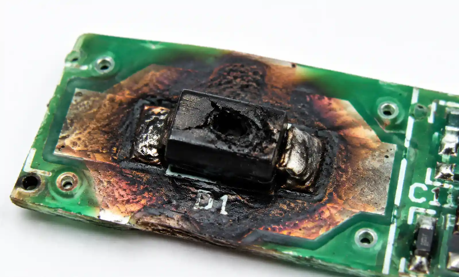
What happens if I exceed the maximum forward current rating?
Exceeding IF causes junction temperature to rise beyond the rated maximum (typically 125-150°C). This accelerates degradation mechanisms, increases forward voltage drop, and can cause catastrophic thermal runaway. Short-term overload capability is defined by IFSM (surge current) rating, typically valid for 8.3ms (half-cycle at 60Hz). Continuous operation above rated IF leads to premature failure. If your application requires higher current, select a diode in a larger package or parallel multiple diodes with current-sharing resistors.
8. Conclusion: SMD Diode Selection Checklist
Selecting the right SMD diode requires balancing electrical performance, thermal management, reliability, and supply chain considerations. Before finalizing your design, verify these critical points:
Electrical Verification: Confirm the diode's reverse voltage rating exceeds maximum circuit voltage by at least 20%. Verify forward current rating (IF) covers your worst-case current including transients. For switching applications above 20kHz, confirm reverse recovery time (trr) is less than 1/5 of the switching period. Check that forward voltage drop (VF) is acceptable for your efficiency target.
Thermal Validation: Calculate junction temperature under worst-case conditions (maximum ambient temperature, maximum current). Ensure TJ remains at least 10°C below the rated maximum. Verify your PCB layout provides adequate copper area for heat dissipation based on the datasheet's thermal resistance specification.
Application Matching: For low-voltage, high-efficiency power supplies, use Schottky diodes. For high-voltage applications above 200V, select fast-recovery or ultra-fast recovery diodes. For voltage regulation and reference, use Zener diodes with appropriate tolerance. For transient protection, select TVS diodes with clamping voltage below your circuit's damage threshold.
Supply Chain Planning: Identify and qualify at least two alternative sources with compatible specifications. Review product lifecycle status to avoid parts approaching obsolescence. Establish supply agreements that align with your production forecast and provide allocation protection.
If you're ready to move forward with SMD diode selection, download detailed datasheets from manufacturers, use parametric search tools from major distributors to compare specifications, or contact FAE teams for application-specific recommendations. For high-reliability designs, request sample parts for thermal and electrical validation testing before committing to production volumes.