SF6 Circuit Breaker Selection Guide: Technical Parameters, Performance Comparison, and Application Considerations
SF6 circuit breakers remain the dominant choice for medium and high-voltage power distribution systems, offering superior arc-quenching performance, compact design, and reliable operation across demanding industrial, utility, and renewable energy applications. This guide helps electrical engineers, power system designers, and procurement teams understand the critical selection parameters, performance trade-offs, and design considerations when specifying SF6 circuit breakers for substations, switchgear, and distribution networks.
Table of Contents
- What is an SF6 Circuit Breaker and Why It Matters
- Key Technical Parameters Explained
- How to Choose the Right SF6 Circuit Breaker for Your Application
- Performance Comparison: SF6 vs Alternative Technologies
- Design Considerations and Common Pitfalls
- Supply Chain and Sourcing Considerations
- FAQ
- Conclusion and Recommended Next Steps
1. What is an SF6 Circuit Breaker and Why It Matters
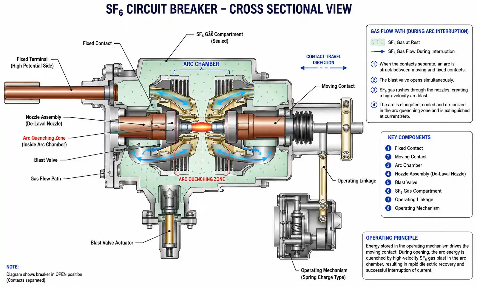
An SF6 circuit breaker uses sulfur hexafluoride gas as the arc-quenching and insulating medium to interrupt fault currents in power systems ranging from 12kV to 800kV. The superior dielectric strength of SF6—approximately 2.5 times that of air at atmospheric pressure—enables compact breaker designs with faster fault clearing times and higher interrupting capacity compared to air-blast or oil circuit breakers.
For power system designers, the primary advantage of SF6 technology lies in its ability to handle high short-circuit currents (up to 63kA or higher) while maintaining a small physical footprint. This becomes critical in urban substations, offshore platforms, and industrial facilities where space constraints and safety considerations drive equipment selection. SF6 breakers also exhibit minimal contact erosion due to the gas's excellent arc-quenching properties, resulting in longer service intervals and lower maintenance costs over the breaker's 30-year typical operational life.
However, SF6 is a potent greenhouse gas with a global warming potential (GWP) of 23,500 times that of CO2, which has led to increasing regulatory scrutiny in Europe, North America, and other regions. The IEC 62271-100 standard now requires enhanced leak detection and monitoring systems, while some jurisdictions mandate SF6 recovery and recycling during maintenance and decommissioning. Understanding these regulatory trends is essential when making long-term capital equipment decisions, particularly for projects with 20+ year asset lifecycles.
2. Key Technical Parameters Explained
When evaluating SF6 circuit breakers, several technical parameters directly impact system protection performance, reliability, and integration complexity. Understanding these specifications helps engineers make informed trade-offs between cost, performance, and operational requirements.
Rated Voltage and Insulation Level
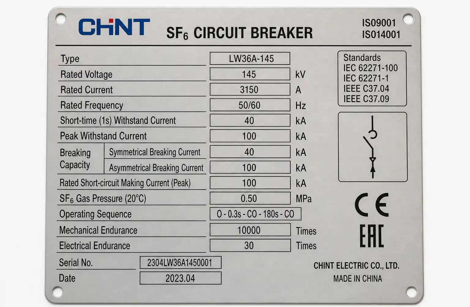
The rated voltage (kV) defines the maximum continuous operating voltage, while the insulation level—expressed as lightning impulse withstand voltage (LI) and power-frequency withstand voltage (PFWV)—determines the breaker's ability to withstand transient overvoltages. For example, a 145kV breaker typically has an LI rating of 650kV and PFWV of 275kV. Selecting a breaker with inadequate insulation coordination can lead to internal flashover during switching surges or lightning strikes, resulting in catastrophic failure.
Rated Short-Circuit Breaking Current
This parameter, measured in kA, indicates the maximum fault current the breaker can safely interrupt. The interrupting capacity must exceed the maximum prospective short-circuit current calculated at the breaker location under worst-case system conditions. A common design mistake is failing to account for future system expansion or generation additions that increase fault levels, leaving the breaker undersized within 10-15 years of commissioning.
Operating Mechanism and Timing
SF6 breakers use spring-charged, hydraulic, or pneumatic operating mechanisms to drive the contacts. The total break time—typically 40-80ms for medium-voltage breakers and 20-40ms for high-voltage units—comprises opening time plus arcing time. Faster operation reduces fault energy but may increase mechanical stress on the breaker components. The mechanical endurance rating (typically 10,000-25,000 operations) and electrical endurance (100-200 short-circuit operations at rated current) define the breaker's expected lifecycle under normal and fault conditions.
SF6 Gas Pressure and Monitoring
SF6 breakers operate at specific gas pressures—typically 0.3-0.8 MPa for medium voltage and higher for EHV applications. Gas density monitoring is critical because even a 10-15% pressure drop can compromise arc-quenching performance and dielectric strength. Modern breakers incorporate density switches with alarm and lockout contacts, preventing closing operations when gas density falls below safe thresholds. The gas compartment design—single-pressure or dual-pressure systems—affects maintenance complexity and leak probability.
| Parameter | Typical Range (Medium Voltage) | Typical Range (High Voltage) | Selection Impact |
|---|---|---|---|
| Rated Voltage | 12-72.5 kV | 145-550 kV | System voltage class, insulation coordination |
| Rated Current | 630-4000 A | 1600-5000 A | Conductor sizing, thermal loading |
| Breaking Capacity | 16-63 kA | 40-80 kA | Fault current withstand, system protection |
| Operating Time | 40-80 ms | 20-50 ms | Protection coordination, fault energy |
| SF6 Pressure | 0.3-0.6 MPa | 0.5-0.8 MPa | Arc extinction, dielectric strength |
| Mechanical Life | 10,000-25,000 ops | 5,000-10,000 ops | Maintenance interval, lifecycle cost |
The selection of these parameters must align with the system studies—load flow, short-circuit, and protection coordination analyses—to ensure the breaker operates within its rated envelope throughout its service life.
3. How to Choose the Right SF6 Circuit Breaker for Your Application
SF6 circuit breaker selection follows a systematic methodology that balances technical requirements, operational constraints, and lifecycle economics. The process begins with defining the application scenario and system parameters.
Step 1: Define System Requirements
Start by gathering the electrical system data: nominal voltage, maximum and minimum fault levels, continuous load current, ambient temperature range (-40°C to +55°C is common), altitude (derating required above 1000m), and seismic requirements if applicable. These parameters establish the minimum rated values the breaker must meet. For renewable energy applications—solar farms or wind plants—pay attention to the breaker's capacitive current switching rating, as cable-connected systems can generate high-frequency transients during energization.
Step 2: Application Scenario Mapping
Different applications prioritize different parameters. Generator circuit breakers require high thermal and dynamic current ratings due to close proximity to the source and asymmetrical fault currents. Feeder breakers in distribution systems need high mechanical endurance due to frequent switching operations. Bus-tie breakers must handle loop-switching duty with phase angle differences across the open contacts. Matching the breaker type to the specific application duty reduces over-specification and cost.
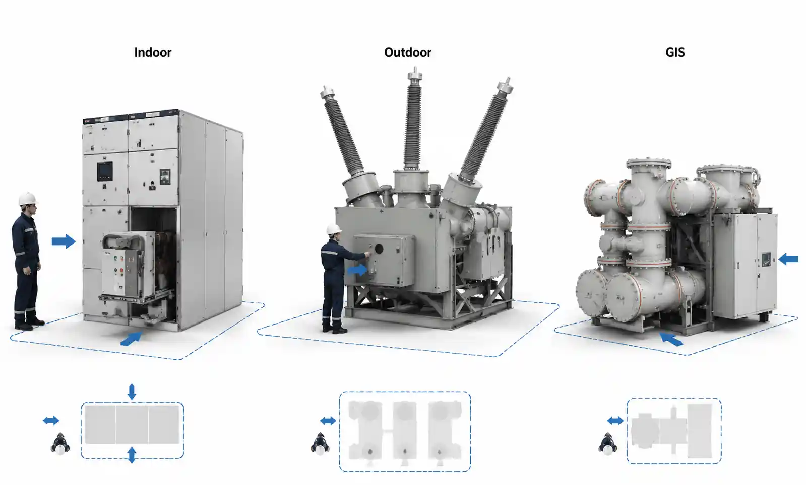
Step 3: Environmental and Installation Constraints
Indoor metal-clad switchgear typically uses fixed-mounted breakers with front or rear access for maintenance. Outdoor substations may use dead-tank or live-tank designs depending on voltage class and climate. Coastal or high-pollution environments require enhanced external insulation (longer creepage distances) and corrosion-resistant coatings. Space-constrained installations benefit from gas-insulated switchgear (GIS) configurations where the breaker, disconnectors, and busbars share a common SF6-filled enclosure.
Step 4: Control and Protection Interface
Modern SF6 breakers integrate with IEC 61850-based substation automation systems, providing digital communication via GOOSE messaging for trip/close commands and breaker status reporting. Verify the breaker's auxiliary contact configuration matches the protection relay input requirements—typically including breaker position (52a/52b contacts), trip coil supervision, SF6 pressure alarm, and spring-charged indication. Some breakers offer condition monitoring capabilities with contact travel measurement, timing analysis, and coil current recording to support predictive maintenance programs.
| Application Type | Key Parameter Priority | Recommended Features |
|---|---|---|
| Generator Breaker | High breaking capacity, asymmetrical rating, mechanical robustness | Out-of-phase switching capability, rapid reclosing, enhanced contact design |
| Transmission Line Breaker | Fast operating time, high voltage class, outdoor duty | Auto-reclose rating, enhanced creepage, seismic qualification |
| Distribution Feeder | High mechanical endurance, frequent switching, moderate breaking duty | Extended maintenance intervals, local/remote control, capacitive switching rating |
| Bus Coupler / Tie Breaker | Loop switching duty, high thermal rating | Phase angle withstand, high short-time current rating |
| Capacitor Bank Breaker | Capacitive inrush current, restrike suppression | Damping resistors, making capacity rating, voltage transient control |
This structured approach reduces the risk of misapplication while identifying opportunities to standardize breaker specifications across multiple feeders or voltage levels, improving spare parts inventory management and maintenance efficiency.
4. Performance Comparison: SF6 vs Alternative Technologies
As environmental regulations tighten, power system engineers increasingly evaluate SF6 circuit breakers against emerging alternatives. Understanding the technical trade-offs helps inform long-term equipment strategies.
| Technology | Dielectric Strength | Interrupting Capacity | Physical Footprint | Environmental Impact | Maturity Level | Typical Cost (Relative) |
|---|---|---|---|---|---|---|
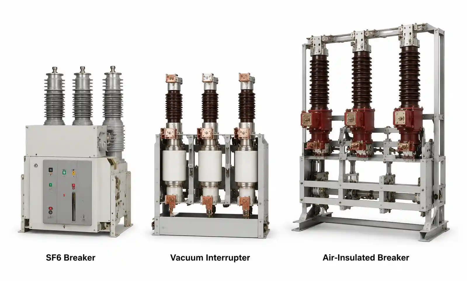
| SF6 Breaker | Excellent (reference) | Up to 80 kA | Compact | High GWP (23,500) | Mature (60+ years) | 1.0x (baseline) |
| Vacuum Breaker | Good (limited to ~52kV) | Up to 63 kA | Very compact | Zero emissions | Mature (<40kV) | 0.7-0.9x |
| Air-Insulated Breaker | Moderate | Up to 63 kA | Large | Zero emissions | Mature | 0.8-1.1x |
| SF6-Free (Fluoronitrile Mix) | Excellent | Up to 63 kA | Compact | Low GWP (<10) | Emerging (5-10 years field data) | 1.2-1.5x |
| Solid Dielectric (Dry Air + Vacuum) | Good | Up to 40 kA | Moderate | Zero emissions | Emerging | 1.1-1.3x |
When SF6 Remains the Optimal Choice
For high-voltage applications (>72.5kV), SF6 breakers currently offer the best combination of interrupting performance, compact design, and field-proven reliability. Transmission and subtransmission systems at 145kV, 245kV, and 550kV voltage classes have limited alternatives with equivalent technical maturity. Retrofit projects replacing aging oil breakers in existing substations often require SF6 technology to fit within the original footprint while meeting modern interrupting capacity requirements.
When to Consider Alternatives
Medium-voltage applications (12-40.5kV) increasingly favor vacuum circuit breakers, which eliminate SF6 emissions entirely while offering excellent reliability for indoor switchgear applications. Vacuum interrupters handle capacitive and inductive switching duties well, making them suitable for motor feeders, capacitor banks, and distribution feeders with frequent operations. The main limitation is voltage class—vacuum technology becomes impractical above 52kV due to contact gap and interrupter size constraints.
Fluoronitrile-based gas mixtures (such as AirPlus or g3) offer SF6-like performance with GWP values below 10, positioning them as drop-in replacements for new switchgear installations. However, these mixtures require careful attention to temperature ratings, as their low-temperature performance differs from pure SF6, potentially requiring gas compartment heaters in cold climates.
5. Design Considerations and Common Pitfalls
Proper SF6 circuit breaker application requires attention to several design details that, if overlooked, can compromise system protection or create long-term operational issues.
Short-Circuit Duty Calculation
A frequent error involves calculating short-circuit current only for existing system conditions, without considering future generation additions, tie-ins with adjacent feeders, or utility supply upgrades that may increase fault levels by 20-40% over the installation's lifetime. IEC standards recommend applying a 10% safety margin to the calculated maximum fault current when selecting breaker ratings, but this may be insufficient for rapidly developing industrial complexes or renewable energy zones with planned expansion.
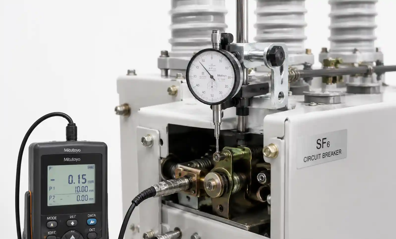
Contact Travel and Timing Verification
SF6 breakers must achieve specified contact travel distance to ensure reliable arc extinction within the rated arcing time. During commissioning, contact travel measurement and timing tests verify the operating mechanism delivers adequate kinetic energy to overcome contact resistance and gas pressure forces. Deviations of more than 10-15% from nameplate values may indicate mechanical issues—weak closing springs, hydraulic system leaks, or worn linkages—that degrade interrupting performance.
SF6 Gas Handling and Leak Management
Gas leakage rates for properly maintained SF6 breakers should remain below 0.5% per year. Higher leak rates—often occurring at gasket interfaces, bushings, or operating mechanism penetrations—not only pose environmental compliance issues but also compromise breaker reliability. Gas density interlocks prevent breaker operation when pressure drops below safe thresholds, creating forced outages if leaks go undetected. Implementing periodic leak detection using infrared cameras or sniffer instruments should be part of routine maintenance procedures.
Parallel Operation and Synchronizing
When paralleling sources or closing loops, the SF6 breaker must withstand the transient current and electromagnetic forces generated by phase angle differences across open contacts. Bus-tie and generator synchronizing breakers require enhanced making capacity ratings—often 2.5-2.7 times the rated breaking current—to handle the first peak current during out-of-phase closing. Failing to specify adequate making capacity can weld contacts closed or fracture operating mechanism components during the first major switching event.
Altitude and Temperature Derating
SF6 dielectric strength decreases with reduced gas density at high altitude. Installations above 1000m require altitude correction factors applied to insulation levels and interrupting capacity, typically resulting in 1-2% derating per 100m elevation. Similarly, extreme ambient temperatures affect SF6 pressure—installations in desert climates (+55°C) or arctic regions (-50°C) may require temperature-compensated density monitoring to prevent nuisance alarms or compromised performance.
| Common Pitfall | Technical Impact | Prevention Strategy |
|---|---|---|
| Undersized breaking capacity | Contact welding, explosion risk, protection failure | Include 10-15% margin, account for system expansion |
| Inadequate making capacity | Operating mechanism damage during loop closing | Verify duty cycle matches application (standard vs. special) |
| Poor gas compartment sealing | Performance degradation, forced outages | Quarterly leak detection, gasket replacement during major overhauls |
| Incorrect TRV rating | Restrike, overvoltage, insulation failure | Match breaker TRV curve to system characteristics (cable vs. overhead line) |
| Insufficient contact travel | Incomplete arc extinction, contact erosion | Commissioning tests, periodic mechanical inspections |
Addressing these considerations during specification and commissioning phases prevents costly retrofits or premature breaker failures.
6. Supply Chain and Sourcing Considerations
SF6 circuit breaker procurement involves longer lead times and more complex logistics than commodity electrical equipment, requiring careful planning for capital projects and maintenance programs.
Lead Time and Manufacturing Capacity
Standard medium-voltage SF6 breakers (12-40.5kV) typically have 16-24 week factory lead times for major manufacturers, while high-voltage units (145kV and above) extend to 40-60 weeks due to custom engineering, factory testing, and transportation logistics. Project schedules should account for these timelines plus shipping (4-8 weeks for overseas suppliers) and site commissioning (2-4 weeks). Rush orders or expedited production can reduce lead times by 20-30% but often carry premium pricing of 15-25%.
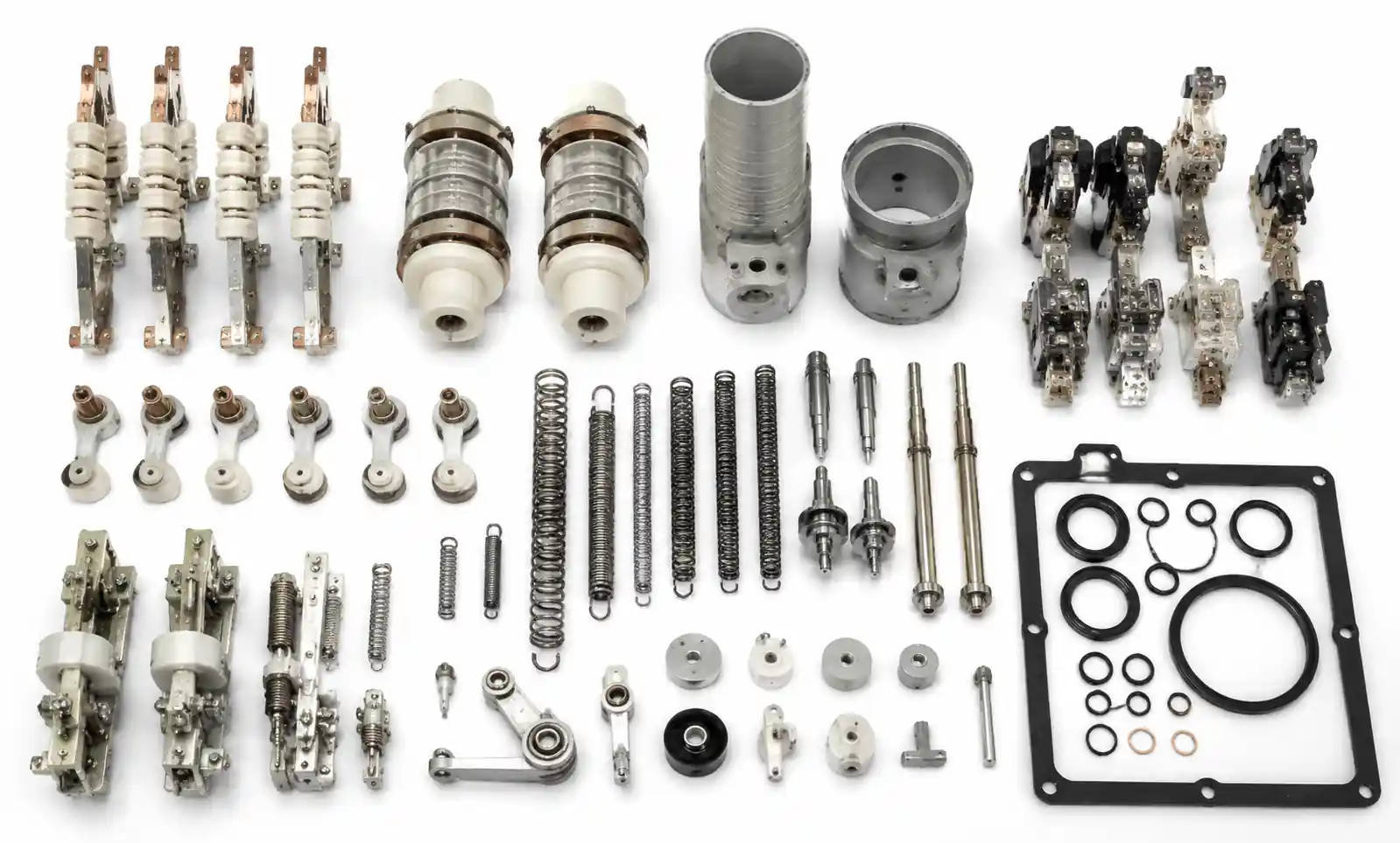
Spare Parts and Service Support
SF6 breaker maintenance requires manufacturer-specific parts—contact sets, operating mechanism components, SF6 gas, and sealing elements—that may have limited interchangeability between suppliers or even breaker models within the same manufacturer's product line. Establishing a spare parts inventory strategy should consider critical components with long replacement lead times (operating mechanisms, arc chambers) versus consumables with shorter availability (auxiliary switches, control wiring). Many utilities standardize on 2-3 preferred manufacturers to minimize inventory complexity while maintaining competitive pricing.
Environmental Compliance and SF6 Recovery
Jurisdictions including the EU (F-Gas Regulation), California (AB 32), and others mandate SF6 recovery during maintenance, breaker refurbishment, and decommissioning. Procurement specifications should verify the manufacturer provides proper gas handling equipment, training, and documentation for regulatory compliance. Some manufacturers offer SF6 reclamation services or buyback programs for end-of-life equipment, reducing disposal costs and environmental liability.
Alternative Sourcing Strategies
For cost-sensitive projects or regions with extended lead times, refurbished SF6 breakers offer 40-60% cost savings compared to new units. Reputable refurbishment facilities perform complete mechanical and electrical overhauls, replacing wear components and retesting to original factory specifications. The key risk mitigation involves verifying the refurbisher's quality management system (ISO 9001 certification) and obtaining test reports documenting interrupting capacity validation and gas tightness verification.
| Sourcing Factor | Considerations | Impact on Total Cost of Ownership |
|---|---|---|
| Manufacturer Selection | Global vs. regional brand, service network, spare parts availability | 15-25% lifecycle cost variation |
| Lead Time | Standard vs. expedited, project schedule risk | Premium pricing, potential delay costs |
| Warranty Terms | 1-3 years typical, extended warranties available | Risk transfer, predictable budgeting |
| Compliance Documentation | IEC/IEEE test reports, type test certificates, environmental certifications | Regulatory acceptance, project approval |
| Training and Commissioning | Factory-provided vs. third-party, ongoing support | Operational reliability, maintenance efficiency |
Balancing these factors requires collaboration between engineering, procurement, and operations teams to optimize initial capital cost against long-term reliability and maintenance considerations.
7. FAQ
What is the typical lifespan of an SF6 circuit breaker?
SF6 circuit breakers have a design life of 30 years under normal operating conditions, with actual service life depending on operating duty, maintenance quality, and environmental factors. Mechanical life typically ranges from 10,000 to 25,000 operations, while electrical life is rated for 100-200 full short-circuit interruptions at rated current. Many breakers remain in service beyond 30 years with major overhauls at 15-20 year intervals, including contact replacement and operating mechanism refurbishment.
How often does an SF6 circuit breaker require maintenance?
Maintenance intervals vary by manufacturer and application severity but typically follow a 3-5 year cycle for routine inspections including gas density verification, contact resistance measurement, and operating mechanism lubrication. Major overhauls occur at 10-15 year intervals, involving contact replacement, operating mechanism inspection, and gas compartment retesting. High-duty applications (generator breakers, frequent switching) may require shorter intervals based on operation counters rather than calendar time.
Can SF6 circuit breakers be retrofitted with SF6-free gas alternatives?
Retrofitting existing SF6 breakers with alternative gases is generally not feasible due to differences in gas properties, required pressures, and arc-quenching characteristics. Fluoronitrile-based mixtures have different boiling points and dielectric performance curves compared to SF6, requiring breaker redesign. The practical approach involves equipment replacement at end-of-life rather than retrofit, though some manufacturers offer trade-in programs to incentivize migration to low-GWP technologies.
What are the environmental regulations affecting SF6 circuit breaker usage?
The EU F-Gas Regulation restricts SF6 equipment sales and mandates leak detection, repair, and reporting for installations containing more than 5 kg of SF6. California's AB 32 imposes similar requirements with annual reporting to the Air Resources Board. Many regions require SF6 recovery and recycling during maintenance, with certified handling procedures and documentation. Future regulations may further restrict new SF6 installations in medium-voltage applications where alternatives exist, while permitting continued use for high-voltage systems lacking mature alternatives.
How do I verify an SF6 circuit breaker's interrupting capacity?
Interrupting capacity is verified during factory type testing per IEC 62271-100 or IEEE C37.09, with test certificates documenting successful interruption at rated short-circuit current and specified transient recovery voltage (TRV). Routine production testing verifies mechanical operation and dielectric strength but does not include full short-circuit testing. For installed breakers, periodic high-current injection testing or contact resistance measurement can assess contact condition, but full interrupting capacity validation requires specialized high-power test facilities available only at factory or independent testing laboratories.
What is the difference between single-pressure and dual-pressure SF6 breakers?
Single-pressure breakers use the same SF6 gas pressure for both arc extinction and insulation, simplifying design and reducing leak points. Dual-pressure designs use high-pressure SF6 for arc quenching (typically 1.4-1.6 MPa) and lower pressure for insulation (0.3-0.5 MPa), offering superior interrupting performance but with increased mechanical complexity. Modern breakers predominantly use single-pressure designs with puffer or self-blast arc extinction mechanisms, providing adequate performance with better reliability and lower maintenance requirements.
8. Conclusion and Recommended Next Steps
SF6 circuit breakers remain the technology of choice for high-voltage power systems where compact design, high interrupting capacity, and proven reliability are essential. For medium-voltage applications, engineers should evaluate vacuum or SF6-free alternatives against SF6 technology based on specific duty requirements, environmental regulations, and lifecycle cost considerations.
When specifying SF6 breakers for your next project, prioritize three critical factors: accurate short-circuit duty calculation with adequate margin for system expansion, proper application matching (generator duty, feeder duty, capacitive switching), and environmental compliance strategy including gas monitoring and recovery procedures. For retrofit projects replacing aging equipment, verify the new breaker's physical dimensions, control interface compatibility, and interrupting capacity against both current and projected system fault levels.
If your application requires high-voltage interruption (>72.5kV), SF6 technology offers the most mature and cost-effective solution. For medium-voltage installations in regions with strict SF6 regulations, consider vacuum circuit breakers or fluoronitrile-based alternatives to future-proof your installation against evolving environmental standards.
Before finalizing your selection, download detailed technical specifications from qualified manufacturers, consult with field application engineers on specific duty cycle requirements, and request type test certificates documenting compliance with IEC 62271-100 or IEEE C37.09 standards. For complex applications involving generator protection, capacitor bank switching, or outdoor extreme environment installations, early engagement with the breaker manufacturer's technical team helps identify potential application issues and optimize the specification.