




Thermal Management Components: Heat Sinks, Fans, and TIMs Selection
Thermal failures account for 55% of all electronic component failures in production environments. In 2026, as power densities in semiconductors continue rising—with GPUs now exceeding 450W TDP and server processors reaching 350W—proper thermal management has become critical for hardware reliability and performance. If you want to prevent thermal throttling, extend component lifespan, and maintain system stability, you need to understand heat sink design, active cooling selection, and thermal interface material properties.
This guide draws from real thermal engineering experience across consumer electronics, industrial systems, and data center deployments, covering selection criteria that prevent thermal failures while optimizing cost and physical constraints.
Table of Contents
- Understanding Thermal Management Fundamentals
- Heat Sink Selection and Design
- Active Cooling: Fan Selection Criteria
- Thermal Interface Materials (TIMs) Comparison
- Integrated Thermal Module Design
- Performance Verification and Testing
- FAQs
- Conclusion
Understanding Thermal Management Fundamentals
Thermal management is the systematic process of controlling component operating temperatures through heat transfer mechanisms: conduction, convection, and radiation. This involves selecting appropriate passive cooling structures (heat sinks), active cooling devices (fans), and thermal interface materials that together maintain junction temperatures within datasheet specifications.
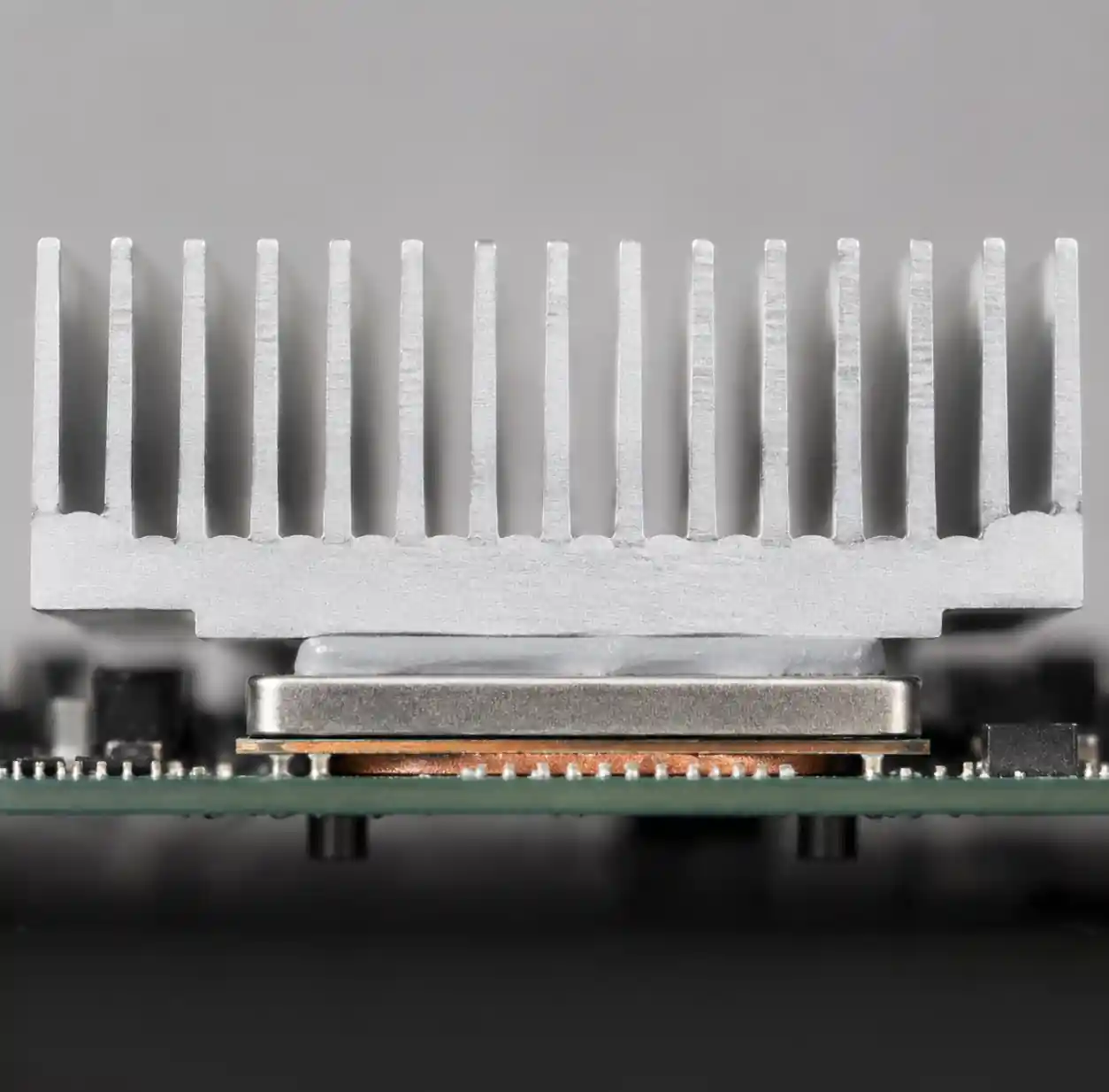 Heat transfer mechanism from semiconductor junction through heat sink to ambient air
In electronics, heat flows from the semiconductor junction through package materials, across thermal interface material, into a heat sink base, through fin structures, and finally into ambient air. Each interface creates thermal resistance measured in °C/W—the temperature rise per watt of power dissipation. Your total thermal resistance determines whether a component stays within its maximum junction temperature (typically 85-125°C for commercial parts).
The fundamental equation governing thermal design is straightforward: Tj = Ta + (θja × P), where Tj is junction temperature, Ta is ambient temperature, θja is junction-to-ambient thermal resistance, and P is power dissipation. To keep Tj below maximum ratings, you must reduce θja through better thermal management components when power or ambient temperature increases.
Heat Sink Selection and Design
Material Selection and Thermal Conductivity
Heat sink performance depends heavily on material thermal conductivity. Aluminum alloys (6061, 6063) offer 160-200 W/m·K conductivity at lower cost and weight, making them standard for most applications. Copper provides 385-400 W/m·K conductivity—nearly double aluminum—but costs 3-4× more and weighs 3.3× more per volume.
| Material | Thermal Conductivity (W/m·K) | Density (g/cm³) | Relative Cost | Best Applications |
|---|---|---|---|---|
| Aluminum 6061 | 167 | 2.70 | 1.0× | General electronics, cost-sensitive designs |
| Aluminum 6063 | 201 | 2.70 | 1.1× | Extruded heat sinks, consumer products |
| Copper C11000 | 391 | 8.96 | 3.5× | High-power processors, localized hot spots |
| Copper-Aluminum Hybrid | 250-300 | 4.5-5.5 | 2.0× | Optimized weight/performance balance |
For most applications under 100W, aluminum provides sufficient performance at acceptable cost. Copper makes sense for high-power density applications (>50W/cm²) where the junction-to-case thermal resistance dominates, or when heat sink volume is severely constrained. Hybrid designs use copper base plates for heat spreading with aluminum fins for convective surface area.
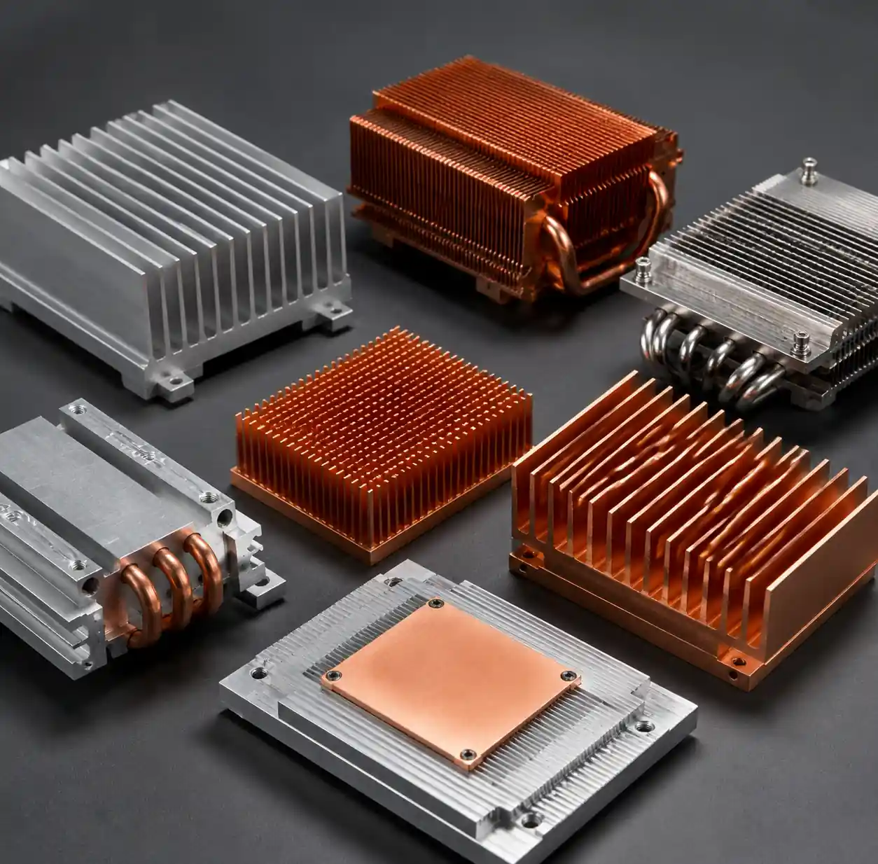 Aluminum and copper heat sinks showing material and design differences
Fin Geometry and Surface Area
Heat sink effectiveness depends on maximizing surface area while maintaining adequate airflow between fins. Fin spacing must balance these competing requirements—closer fins increase surface area but restrict airflow, while wider spacing improves airflow but reduces total area.
For natural convection (passive cooling), maintain minimum 8-10mm fin spacing to allow proper air circulation. Fin height typically ranges 25-40mm to create sufficient thermal chimney effect. Natural convection heat sinks achieve thermal resistance of 5-15°C/W for typical sizes.
Active cooling with forced airflow allows tighter fin spacing of 2-5mm, dramatically increasing surface area density. At moderate airspeeds (2-3 m/s), fin efficiency remains high with 3mm spacing. This enables thermal resistance below 1.0°C/W for compact, high-performance heat sinks.
Base Plate Flatness and Contact
Heat sink base flatness directly impacts thermal interface performance. Manufacturing tolerances should maintain flatness within 0.05mm across the contact area. Surface roughness below 1.6 µm Ra ensures good TIM contact without excessive voids.
When mounting heat sinks, apply uniform clamping pressure across the contact area. Most designs require 40-80 psi (275-550 kPa) mounting pressure for optimal TIM performance. Uneven pressure creates air gaps that dramatically increase thermal resistance—a 0.1mm air gap adds approximately 5°C/W resistance.
Active Cooling: Fan Selection Criteria
Airflow and Static Pressure Requirements
Fan selection requires balancing airflow volume (CFM or m³/h) against static pressure capability. Heat sinks with dense fin arrays create high impedance, demanding fans with strong static pressure performance rather than maximum free-air flow.
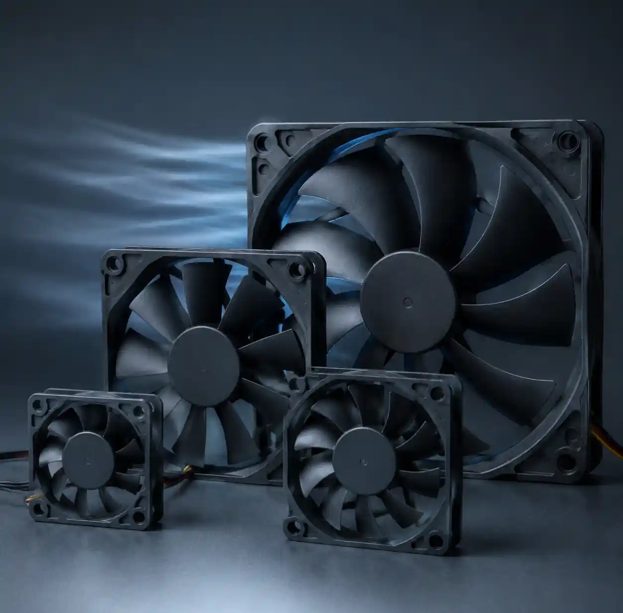 Cooling fans of various sizes showing blade design and airflow characteristics
Review the fan's pressure-flow (P-Q) curve to understand performance at your system's impedance. A fan rated 50 CFM at zero static pressure might deliver only 25 CFM when working against a dense heat sink. Calculate your system's impedance curve and find the intersection point with the fan's P-Q curve to determine actual operating airflow.
For heat sinks with 3mm fin spacing, target fans providing at least 0.2-0.4 inches H₂O (50-100 Pa) static pressure. Natural convection heat sinks require lower pressure but higher volume flow for effective cooling.
Fan Size and Noise Considerations
Larger diameter fans move equivalent air volume at lower RPM, reducing acoustic noise significantly. An 80mm fan achieves similar airflow to a 60mm fan while running 30-40% slower, cutting noise levels by 6-8 dBA.
| Fan Size | Typical Airflow Range | Operating RPM | Noise Level | Best Use Cases |
|---|---|---|---|---|
| 40mm × 40mm | 5-15 CFM | 4,000-8,000 | 28-40 dBA | Compact embedded systems, spot cooling |
| 60mm × 60mm | 15-35 CFM | 3,000-6,000 | 25-38 dBA | Small enclosures, telecom equipment |
| 80mm × 80mm | 30-60 CFM | 2,000-4,000 | 20-32 dBA | Desktop computers, industrial controllers |
| 120mm × 120mm | 50-120 CFM | 1,200-2,500 | 18-28 dBA | Servers, workstations, quiet operation priority |
Consumer electronics targeting quiet operation should limit fan noise to 25-30 dBA at normal operating speeds. Industrial applications tolerate 35-45 dBA, while data center equipment may run at 45-55 dBA under load. Pulse-width modulation (PWM) control allows dynamic speed adjustment, running fans slower during light loads to reduce noise while maintaining cooling capacity for peak demands.
Bearing Technology and Lifespan
Fan bearing type determines operating lifespan and reliability. Sleeve bearings cost least but typically last 30,000-50,000 hours at 40°C ambient. Ball bearings extend life to 50,000-70,000 hours with better high-temperature performance. Fluid dynamic bearings (FDB) offer 70,000-100,000+ hour lifespans with low noise, ideal for continuous operation systems.
Calculate expected fan lifespan at your actual operating temperature using the vendor's temperature derating curve. Every 10°C ambient increase typically halves bearing life, so a 50,000-hour fan at 40°C may only achieve 25,000 hours at 50°C ambient.
Thermal Interface Materials (TIMs) Comparison
TIM Categories and Performance Characteristics
Thermal interface materials fill microscopic air gaps between component surfaces and heat sink bases. Air's thermal conductivity (0.026 W/m·K) is roughly 100× worse than typical TIMs, making proper interface material selection critical for thermal performance.
Thermal Grease (Paste): Remains the most common TIM for mainstream applications. Modern thermal pastes achieve 3-12 W/m·K conductivity depending on filler materials. Silver-filled pastes reach 8-12 W/m·K, while ceramic (aluminum oxide, zinc oxide) formulations provide 3-6 W/m·K at lower cost. Thermal grease wets surfaces thoroughly when proper mounting pressure is applied, achieving bond line thickness of 25-75 µm.
Application requires careful technique—too little paste creates coverage gaps, while excessive paste squeezes beyond the die area without improving performance. The optimal application forms a thin, even layer covering the entire die surface when the heat sink is mounted. Grease performance degrades over 3-5 years as volatile components evaporate, requiring reapplication for long-term systems.
Thermal Pads: Pre-cured silicone or non-silicone polymer pads offer convenience for manufacturing. Typical thermal conductivity ranges 3-8 W/m·K for standard pads, with premium non-silicone materials reaching 10-15 W/m·K. Pads work well for components with variable heights or where rework capability matters.
The tradeoff is higher thermal resistance than grease—pads typically add 0.2-0.5°C/W more resistance than equivalent paste due to thicker bond lines (100-500 µm) and lower conformability. Non-silicone pads consistently outperform silicone equivalents, making them preferred for performance-critical applications.
Phase Change Materials (PCM): These solid pads soften at 50-60°C operating temperature, conforming to surface irregularities like grease while maintaining pad handling convenience. PCMs achieve performance between pads and pastes, with thermal conductivity 4-8 W/m·K and bond lines 75-150 µm.
PCMs excel in applications cycling between operating and off states, as the material re-solidifies when cool and re-conforms when heated. This self-healing property maintains performance over thermal cycles better than standard thermal grease.
Thermal Adhesives: Two-part epoxy or acrylic adhesives provide mechanical bonding while conducting heat. Conductivity ranges 1-5 W/m·K—lower than other TIMs but adequate when permanent mounting is required. Thermal adhesives eliminate mechanical fasteners in some designs but prevent future rework or component replacement.
TIM Selection Decision Framework
Choose your thermal interface material based on performance requirements, manufacturing process, and lifecycle expectations:
- Peak performance, manual assembly, periodic maintenance: Thermal grease (8-12 W/m·K)
- Automated assembly, moderate performance, no rework: Thermal pads (5-10 W/m·K)
- Thermal cycling environments, good conformability: Phase change materials (4-8 W/m·K)
- Permanent mounting, no disassembly: Thermal adhesive (1-5 W/m·K)
Surface preparation affects TIM performance regardless of type. Clean both surfaces with isopropyl alcohol to remove oils, oxidation, and particles. Proper surface preparation improves thermal performance by 10-20% compared to uncleaned surfaces.
Integrated Thermal Module Design
System-Level Thermal Architecture
Effective thermal management requires integrated system design rather than isolated component selection. Modern thermal modules coordinate passive structures, active cooling, and interface materials into unified assemblies optimized for specific thermal loads.
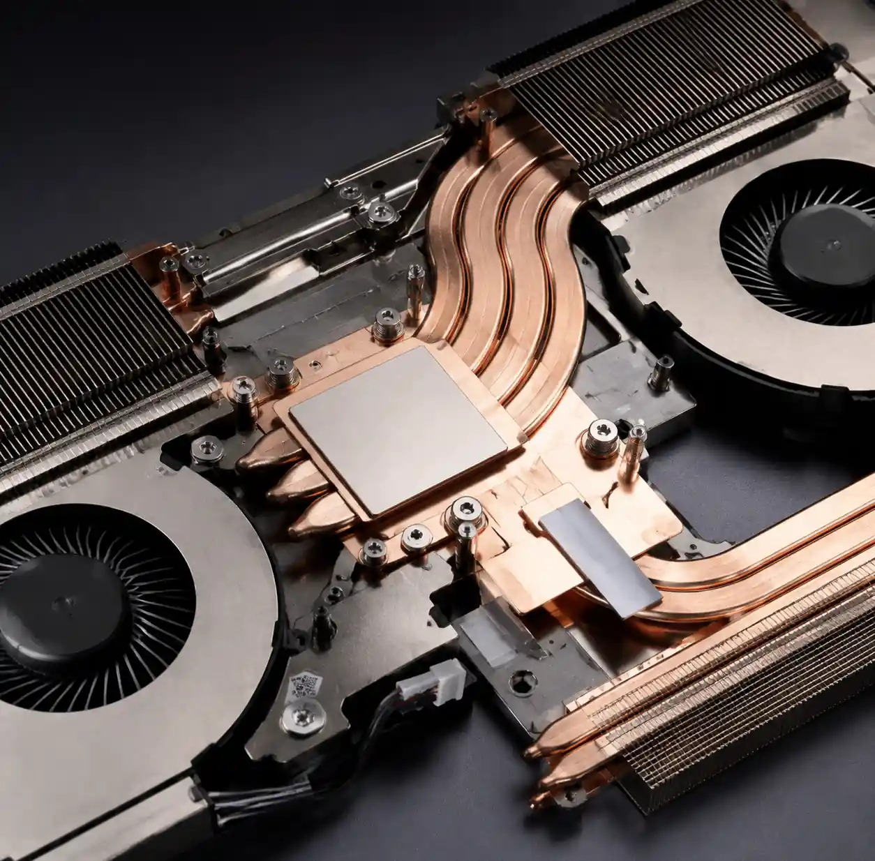 Integrated thermal module with heat pipes and vapor chamber technology
High-performance systems increasingly use heat pipe technology to transport heat from concentrated sources to larger heat sink structures. Heat pipes achieve 10,000-100,000 W/m·K effective thermal conductivity—far exceeding solid conductors—by evaporating working fluid at the hot end and condensing at the cool end.
Vapor chamber technology extends heat pipe principles across a two-dimensional surface, providing exceptional heat spreading for large die areas. Modern GPUs and high-power processors use vapor chambers to spread 300-450W heat loads across heat sink bases measuring 100-150cm², preventing hot spots that would occur with solid copper alone.
Airflow Path Optimization
System thermal performance depends not just on individual components but on coordinated airflow management. Design clear intake and exhaust paths with minimal obstruction. Position fans to create positive pressure (pushing air in) or negative pressure (pulling air out) depending on filtration and dust management needs.
Maintain consistent airflow direction through the chassis—mixing intake and exhaust fans in conflicting orientations creates turbulence and reduces effective cooling. Use CFD analysis or physical prototyping to identify recirculation zones and stagnant air pockets where components receive inadequate cooling despite adequate overall airflow.
For rack-mounted equipment, consider hot aisle / cold aisle data center configurations. Front-to-back airflow with cold aisle intake and hot aisle exhaust optimizes cooling efficiency at the facility level.
Performance Verification and Testing
Thermal Resistance Measurement
Verify thermal management system performance through controlled testing before production deployment. Measure junction temperature under known power dissipation and ambient conditions, then calculate actual thermal resistance: θja = (Tj - Ta) / P.
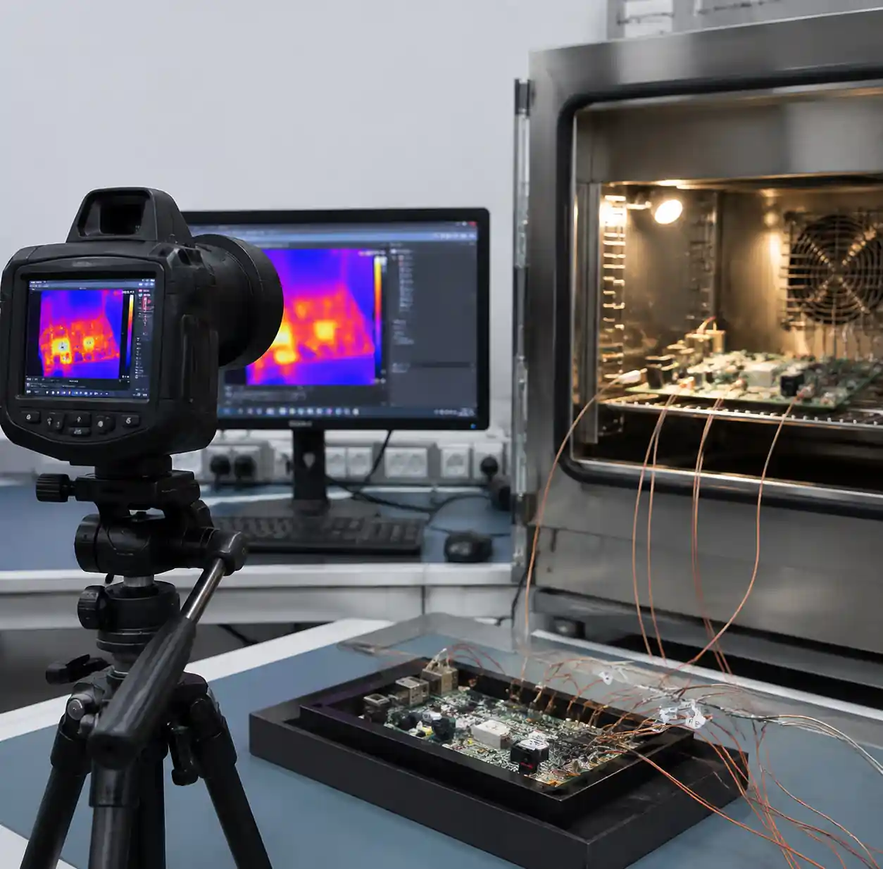 Thermal testing equipment showing temperature measurement and thermal imaging
Use thermocouples attached to package surfaces for discrete components, or software sensor reporting for processors with integrated thermal diodes. Log temperatures under steady-state operation (30-60 minutes at full load) and during thermal transients to understand both continuous and burst thermal response.
Compare measured thermal resistance against your design targets. If measured values exceed predictions by >20%, investigate mounting pressure, TIM application, airflow restrictions, or heat sink contact issues.
Thermal Imaging and Hot Spot Detection
Infrared thermal cameras reveal temperature distribution across components and heat sinks, identifying localized hot spots invisible to single-point measurements. Scan boards under operating load to verify even temperature distribution and identify cooling deficiencies.
Common issues revealed by thermal imaging include blocked airflow creating hot zones, inadequate TIM coverage leaving hot spots on die edges, and uneven heat sink contact causing temperature gradients across the base plate. Address these issues before production qualification to prevent field failures.
Reliability Testing and Accelerated Life
Subject thermal management systems to accelerated life testing under elevated temperatures and thermal cycling. Standard automotive qualification requires 1,000+ thermal cycles from -40°C to +125°C, while consumer electronics typically test 500-1,000 cycles from 0°C to +85°C.
Monitor thermal performance degradation over cycle testing. Increases in thermal resistance indicate TIM pump-out, fan bearing wear, or heat sink mounting relaxation. Well-designed thermal systems should show <10% thermal resistance increase over qualification testing.
FAQs
Q: How do I calculate required heat sink thermal resistance for my application?
Calculate using the formula: θsa = (Tj,max - Ta,max) / P - θjc - θtim, where θsa is heat sink thermal resistance, Tj,max is maximum junction temperature, Ta,max is maximum ambient temperature, P is power dissipation, θjc is junction-to-case resistance (from datasheet), and θtim is thermal interface resistance (typically 0.2-0.5°C/W). Select a heat sink with θsa rating at least 20% better than calculated to provide margin.
Q: What thermal conductivity rating should I look for in thermal paste?
For mainstream electronics (CPUs, GPUs, power semiconductors), thermal paste with 5-8 W/m·K conductivity provides excellent performance at reasonable cost. Premium pastes reaching 8-12 W/m·K offer 2-5°C improvement at 2-3× the price—worthwhile for extreme overclocking or maximum-performance systems, but diminishing returns for typical applications. Avoid thermal compounds below 3 W/m·K, which significantly underperform.
Q: Should I use copper or aluminum heat sinks?
Choose aluminum for most applications under 100W where cost and weight matter. Use copper when junction-to-case thermal resistance dominates your thermal budget (typically high-power density applications >50W/cm²), or when heat sink volume is severely constrained. Copper's 2× higher conductivity rarely justifies 3-4× cost and 3.3× weight unless you specifically need maximum thermal performance in minimal space.
Q: How do I determine if I need active cooling or if passive convection is sufficient?
Calculate required thermal resistance: θ = (Tj,max - Ta,max) / P. Compare against available passive heat sinks—natural convection typically achieves 5-15°C/W depending on size and orientation. If required θ falls below 5°C/W, you likely need forced air cooling. Also consider that vertical orientation improves natural convection by 20-30% compared to horizontal mounting, while enclosed spaces dramatically reduce passive cooling effectiveness.
Q: What's the expected lifespan of thermal paste, and when should it be replaced?
Quality thermal paste maintains performance for 3-5 years under normal operating conditions (junction temperatures 60-85°C). High-temperature operation (>90°C continuous) accelerates degradation to 2-3 years as volatile components evaporate. Signs requiring replacement include rising component temperatures under consistent load, visible paste dry-out or cracking, or performance restoration after remounting. Consumer electronics rarely require paste replacement within product lifespan, but servers and workstations running 24/7 benefit from reapplication every 3-4 years.
Q: How tight should heat sink mounting pressure be?
Most thermal interface materials require 40-80 psi (275-550 kPa) mounting pressure for optimal performance. Over-tightening (>100 psi) can damage component packages without improving thermal performance, while under-tightening creates air gaps that dramatically increase thermal resistance. Use calibrated spring-loaded fasteners or torque-controlled screws to ensure consistent pressure. If using thermal pads, follow vendor's compression specifications—typically 10-30% compression of original pad thickness.
Conclusion
Thermal management directly affects system reliability and performance. Heat sink material, geometry, and surface preparation set baseline thermal resistance. Active cooling balances airflow against noise and power limits. Thermal interface materials bridge the component-heat sink junction, with selection depending on performance, manufacturing, and lifecycle needs.
Effective design integrates these elements into coordinated modules. Material choice—aluminum versus copper—depends on power density and space, not assumptions. Fan sizing balances cooling and acoustics, with larger fans achieving lower noise at equivalent airflow.
Testing—thermal resistance measurements, infrared imaging, and accelerated life testing—confirms real-world performance and prevents field failures from thermal throttling or degradation.
For reliable electronic components with proper thermal specs, Hitop Tech Limited offers procurement services and technical support. Our team assists with thermal characterization and cooling solutions. Contact us today for sourcing and consultation.
