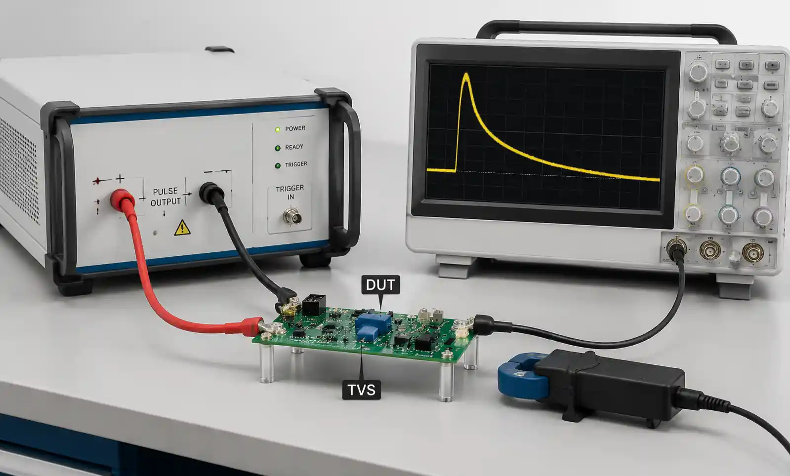
Transient Voltage Protection: Complete Selection Guide for Electronic Design Engineers (2026)
When a power surge hits your circuit, you've got milliseconds—sometimes nanoseconds—to save your design. Transient voltage events are a leading cause of field failures in everything from automotive ECUs to industrial sensors. This guide cuts through the datasheet noise and tells you what actually matters when selecting transient voltage protection.
Table of Contents
- Key Technical Parameters
- How to Choose the Right Component
- Performance Comparison Table
- Design Considerations and Common Pitfalls
- Application-Specific Selection Guide
- FAQ
- Conclusion
Key Technical Parameters
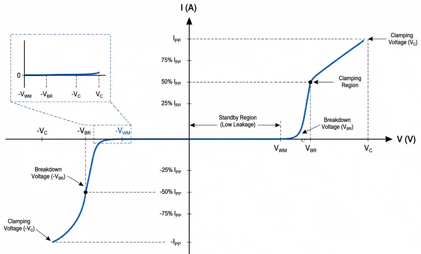
Breakdown Voltage (VBR): The voltage where the device starts conducting. Must sit above your max normal operating voltage with margin. Automotive 12V rails typically need 15-17V VBR to handle cold-crank and alternator ripple. Rule: VBR ≥ 1.2× max operating voltage.
Clamping Voltage (VC): The voltage your downstream IC actually sees during a transient. Critical spec: VC must stay below your IC's absolute maximum rating, with margin for trace inductance. For a 3.3V logic IC with 4.5V abs max, VC needs to be well under 4V after accounting for parasitics.
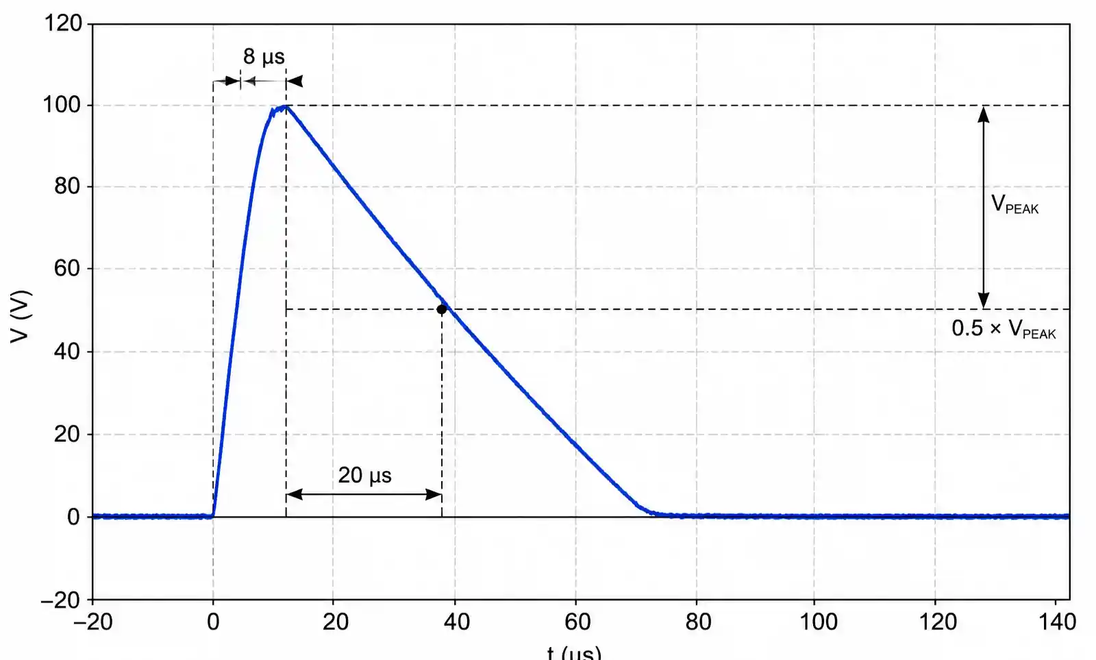
Peak Pulse Current (IPP): Maximum transient current the device can clamp at specified pulse duration (usually 8/20µs). Automotive load dump can hit 50-150A. ESD events per IEC 61000-4-2 reach 15-30A. Don't underspecify IPP—this is the #1 cause of field failures.
Response Time: TVS diodes respond in <1ns—essential for fast logic and RF. MOVs respond in 1-25ns. GDTs are slowest (100ns-1µs) but handle the most energy. For USB 3.0 at 5Gbps, you need <0.3pF capacitance and <0.5ns response.
Standby Leakage Current: Current flowing under normal operation. Premium TVS diodes spec <1µA. In battery-powered IoT devices, leakage current directly impacts battery life—every microamp counts.
How to Choose the Right Component
Step 1: Define your threat model. Automotive needs load dump protection (ISO 7637-2: 60-100V spikes, 100-400ms). Industrial faces inductive switching and lightning surges (IEC 61000-4-5 Level 4: 4kV). Consumer USB needs ESD (IEC 61000-4-2 Level 4: 8kV contact). Each threat dictates different voltage, current, and energy requirements.
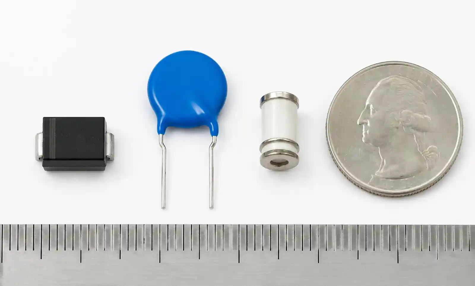
Step 2: Match technology to application. TVS diodes excel at low-voltage (5-100V), fast response, precise clamping. Use for data lines (USB, HDMI, Ethernet), precision analog, tight clamping voltage requirements. MOVs suit higher voltage (120VAC, 48V telecom) where energy handling > clamping precision. GDTs handle the highest energy (up to 10kA) but with slow response—use as primary protection for lightning threats, always pair with TVS for secondary clamping.
Step 3: Calculate energy rating. For an 8/20µs pulse at 10A through 20V clamp, energy is about 0.5J. Automotive load dump (87V for 400ms at 10A) can hit 50-100J—you need purpose-built automotive TVS rated 200-500J or parallel device arrays.
Step 4: Check parasitic parameters. USB 2.0 tolerates <10pF per line; USB 3.0 SuperSpeed needs <0.3pF. Ethernet 10/100/1000 needs <15pF. Series resistance (0.1-1Ω typical) affects clamping voltage via I×R drop—critical for designs with long PCB traces.
Performance Comparison Table
| Parameter | TVS Diode | MOV | GDT |
|---|---|---|---|
| Response Time | <1 ns | 1-25 ns | 100 ns-1 µs |
| Clamping Voltage | 1.2-1.5× VBR | 2-3× nominal | 200-500V |
| Peak Current | 1A-150A | 100A-10kA | 5kA-20kA |
| Energy Handling | 1J-500J | 10J-1000J | Up to 10kJ |
| Capacitance | 0.05pF-5000pF | 50pF-5000pF | <2pF |
| Leakage Current | <1 µA | 1-10 µA | <1 nA |
| Typical Voltage Range | 5V-600V | 30V-1000V | 75V-5000V |
| Cost per Channel | $0.10-2.00 | $0.20-1.50 | $0.50-5.00 |
| Best Application | Data lines, sensitive analog | AC mains, telecom power | Lightning, outdoor |
Bottom line: USB data lines? TVS only—sub-nanosecond response and low capacitance are non-negotiable. AC mains input? MOVs offer the best energy/cost balance. Outdoor telecom with lightning threat? Staged approach: GDT primary → MOV secondary → TVS final precision clamp.
Design Considerations and Common Pitfalls
PCB Layout Rules: Place protection devices within 5mm of the connector. Every mm of trace adds ~1nH inductance, which creates overshoot: V = L × di/dt. At 10A/ns rise time (typical for ESD), 10mm of trace adds 100V of overshoot beyond the TVS clamping voltage. Use dedicated ground return to chassis ground, not through logic ground plane. Use multiple parallel vias (minimum 3× 0.3mm) directly under the TVS pad.
Mistake #1: Inadequate VBR margin. A TVS with 15V VBR on a 12V automotive rail will conduct during normal alternator operation at 14.5V. Rule: VBR ≥ 1.3-1.5× max normal operating voltage for robust designs.
Mistake #2: Ignoring total clamping voltage. Your IC sees VC + parasitic drops: V_IC = VC + L×di/dt + I×R. For a 10A transient with 1ns rise time through 10mm trace: parasitic ≈ 100V + 0.5V. This is why ultra-low inductance packages (DFN, QFN) and minimal trace length matter.
Mistake #3: Single point of failure. For critical applications, use two TVS devices in series-parallel, or implement a fuse/PTC upstream that opens if the TVS fails short. In automotive ASIL-C/D systems, redundant protection paths with independent failure modes are often required per ISO 26262.

Thermal Management: Repetitive transients generate heat. Calculate P_avg = E_pulse × f_repetition. A 1J transient at 100 pulses/hour = 28mW average. But automotive load dump at 50J can cause junction temperature excursions above 150°C—requiring heat-sinking or uprated devices.
Application-Specific Selection Guide
| Application | Recommended Technology | Key Specs | Notes |
|---|---|---|---|
| USB 2.0 Data Lines | TVS (bidirectional) | <10pF, <1ns response | ESD protection only |
| USB 3.0 / 3.1 Data Lines | TVS (ultra-low C) | <0.3pF, <0.5ns | Use flow-through package |
| Automotive 12V Power | TVS (AEC-Q101) | VBR 15-17V, 200J+ | ISO 7637-2 load dump |
| AC Mains Input | MOV + Fuse | 275VAC, 10kA surge | Add thermal fuse for safety |
| RS-485 / CAN Bus | TVS (bidirectional) | 15-30V, 400W+ | Differential pair protection |
| Ethernet (10/100/1000) | TVS (array) | <15pF per line, 8-channel | Matched capacitance |
| Industrial 24V Power | TVS or MOV | VBR 36-40V, 1500W+ | IEC 61000-4-5 Level 4 |
| Telecom / Outdoor | GDT + MOV + TVS | Staged protection | Lightning-rated (10kA+) |
FAQ
What is the difference between unidirectional and bidirectional TVS diodes?
Unidirectional clamps one polarity—for DC rails where voltage only swings positive. Bidirectional clamps both polarities—for AC lines, differential pairs (RS-485, CAN bus), and any circuit where voltage can swing below ground. USB data lines need bidirectional TVS with symmetric ±5V clamping for both positive and negative ESD strikes.
How do I calculate energy rating for automotive load dump?
ISO 7637-2 Test Pulse 5a: 87V, 400ms, source impedance 0.5-4Ω. Worst-case 174A initially. A TVS clamping at 30V conducts ~114A for 400ms: E = 30V × 114A × 0.4s ≈ 1368J (pulse decays exponentially; actual TVS energy is 50-100J). Select automotive TVS rated for minimum 200J (5kW peak power) with adequate thermal mass.
Can I use MOVs for low-voltage DC power protection?
Not recommended below 24V. MOV clamping is 2-3× nominal voltage, and minimum ratings start around 18V. For a 12V rail, the smallest MOV clamps at 40-60V—too high for most IC abs max (16-20V). TVS diodes provide precise clamping at 1.2-1.5× VBR—superior for low-voltage DC.
What happens if a TVS diode fails?
TVS typically fails short-circuit—safe for downstream circuits but requires upstream overcurrent protection (fuse or PTC) to prevent board damage. MOVs degrade gradually (increasing leakage). GDTs can fail open-circuit, leaving the circuit unprotected. Design for TVS short-circuit failure mode with series resistance or fuses rated above normal current but below damage threshold.
Do TVS diodes degrade over time?
High-quality TVS withstand thousands of transients below rated current without degradation. Any surge exceeding rated energy causes progressive damage—increased leakage, reduced VBR, eventual catastrophic failure. After a suspected over-energy event (lightning strike, major inductive fault), replace TVS devices during next maintenance even if still functional. Periodic leakage current and VBR testing catches early degradation.
How do I select TVS for high-speed data lines?
Three parameters: capacitance (must be under data line budget), series resistance (<1Ω to avoid voltage drop), clamping voltage (below IC abs max but above signal swing). USB 2.0 (480Mbps): <10pF. USB 3.0 SuperSpeed (5Gbps): <0.3pF in flow-through packages. For differential pairs (USB, HDMI, Ethernet), match capacitance between positive and negative lines within 0.05pF to avoid common-mode conversion. Verify with eye diagram testing or TDR.
Conclusion
TVS isn't magic—it's just a component. Pick the right one and lay it out properly, or it won't save your board. For sensitive low-voltage stuff like USB and analog inputs, use fast TVS with low capacitance. For beefier rails like 48V or AC mains, MOVs or staged GDT+TVS setups make more sense.
Three things always bite people: trace inductance adding clamping overshoot, picking a VBR that's too close to the rail, and forgetting that your IC sees VC plus whatever the board parasitics add. Fix those and you've solved 90% of protection problems.
Automotive? AEC-Q101 and 200J minimum for load dump. Battery-powered? Watch your leakage current—1µA adds up over a year. Get datasheets, check the numbers against your actual transient, and test real samples on the bench before you buy reels. The datasheet "typical" values aren't guarantees.