




Unijunction Transistor Selection Guide: Technical Specifications, Applications, and Design Considerations (2026)
The Unijunction Transistor (UJT) remains a critical component in timing circuits, oscillators, and trigger applications. Engineers selecting UJTs for pulse generation, SCR triggering, or voltage-controlled oscillators face decisions about intrinsic standoff ratio, peak-point current, and temperature stability that directly impact circuit reliability and performance. This guide provides technical comparison data, application selection criteria, and design validation parameters needed to specify the right UJT for industrial control systems, power electronics, and signal generation applications.
Table of Contents
- Introduction
- Key Technical Parameters Explained
- How to Select the Right UJT
- Performance Comparison: UJT vs Alternatives
- Design Considerations and Common Mistakes
- Supply Chain and Sourcing Factors
- FAQ
- Conclusion
1. Introduction
Whether you're designing a new SCR firing circuit, replacing obsolete UJT models, or evaluating UJTs against programmable unijunction transistors (PUTs) or microcontroller-based alternatives, this guide covers the performance specifications, cost-availability trade-offs, and design validation steps required for confident component selection. For procurement teams managing long-lifecycle industrial products, we address lead time considerations, cross-reference options, and supply chain strategies for UJT sourcing.
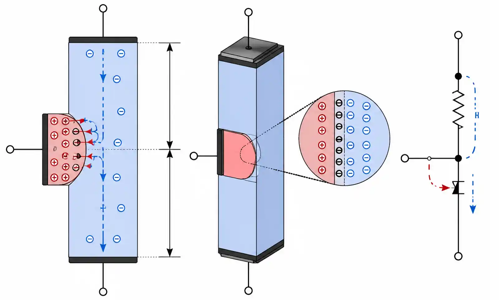
2. Key Technical Parameters Explained
The intrinsic standoff ratio (η) determines trigger voltage and directly affects oscillator frequency stability. Typically ranging from 0.55 to 0.82, it represents the voltage division ratio between the two base terminals. A UJT with η = 0.65 triggers when emitter voltage reaches approximately 65% of interbase voltage plus the emitter-base diode drop (~0.7V). Designers must account for η variation across production lots and temperature ranges when specifying timing accuracy.
Peak-point current (Ip) and valley current (Iv) define the negative resistance region enabling UJT oscillator operation. Ip typically ranges from 2 to 20 µA, while Iv runs 2 to 10 mA. The ratio between these determines the minimum load resistance required for reliable triggering. Lower Ip values (under 5 µA) provide better frequency stability and allow larger timing resistors, reducing capacitor size. Higher valley current ratings ensure adequate gate drive pulse amplitude for SCR triggering.
Interbase resistance (RBB) affects both charging time constant and output pulse characteristics. Standard UJTs exhibit RBB between 4 and 12 kΩ, with tighter tolerance grades available. Temperature coefficient of RBB typically runs +0.7% to +1.0% per °C, creating frequency drift unless compensated. For temperature-stable applications across -40°C to +85°C, specify devices with characterized temperature coefficients and design compensation into the timing network.
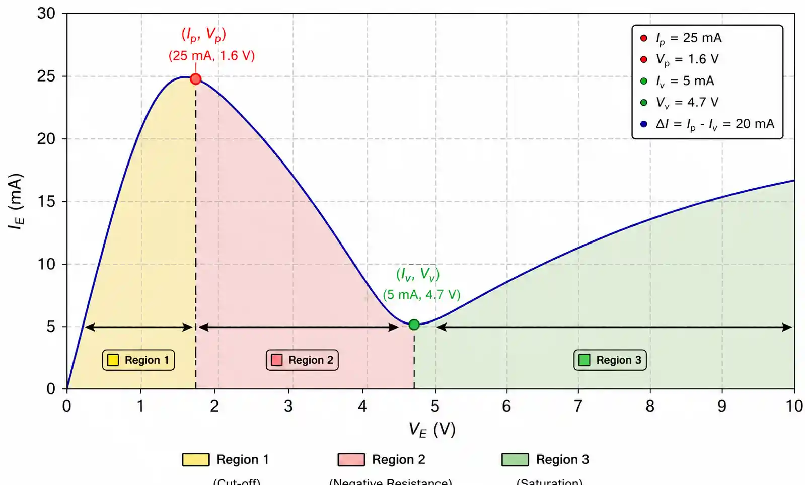
3. How to Select the Right UJT
For SCR/Triac triggering in phase control applications, prioritize valley current capability to ensure adequate gate drive pulse amplitude into typical SCR gate impedances (50–500Ω). UJTs with Iv ratings of 5mA or higher provide reliable triggering with margin. The peak output voltage (Vp) should exceed SCR gate trigger voltage by at least 2V. Common UJT models like 2N6027 deliver peak voltages up to 12V at valley current, suitable for most industrial SCR applications.
For timing and oscillator applications, frequency stability depends primarily on η tolerance and temperature coefficient. For ±5% frequency stability across temperature, specify UJTs with η tolerance of ±10% or tighter and design temperature compensation. Low peak-point current (under 3µA) enables megohm-range timing resistors, reducing capacitor size for long-period timers. The 2N4870 series offers Ip under 2µA with good η tolerance. Calculate timing resistor range using: R = (VBB × η) / Ip, ensuring the result falls within the device's specified operating range.
For voltage-controlled oscillator (VCO) applications, select UJTs with linear η characteristics and tight Ip specifications. Frequency variation with supply voltage follows f ∝ 1/(R×C×VBB), so supply regulation directly affects stability. Applications requiring modulation ranges exceeding 10:1 benefit from PUT alternatives offering better linearity and wider control voltage ranges.
4. Performance Comparison: UJT vs Alternatives
| Device Type | Trigger Voltage Accuracy | Temperature Stability | Component Count | Typical Cost | Best Applications |
|---|---|---|---|---|---|
| Standard UJT (2N2646) | ±15% (η variation) | -0.3 to +0.8%/°C | 3-4 components | $0.30-0.80 | Fixed oscillators, SCR triggering, low-cost timing |
| Programmable UJT (PUT) | ±5% (resistor-set) | ±0.1%/°C (with precision Rs) | 5-7 components | $0.40-1.20 | Precision timing, adjustable frequency, VCO |
| 555 Timer IC | ±1% (with precision Rs) | ±50 ppm/°C (CMOS) | 4-6 components | $0.15-0.50 | General timing, complex waveforms |
| Microcontroller PWM | <0.1% (crystal-based) | ±20 ppm/°C (crystal) | MCU + 2-3 components | $0.50-2.00 | Multiple timing functions, digital control |
| Discrete Comparator | ±2% (resistor-dependent) | ±0.05%/°C (precision op-amp) | 8-12 components | $0.80-2.50 | Precision timing, custom characteristics |
UJTs excel in simple, fixed-frequency pulse generation where component count and cost matter more than precision. A relaxation oscillator built around a 2N2646 requires only the UJT, resistor, and capacitor. Programmable UJTs offer superior flexibility when adjustability or precision matters—setting trigger voltage through external resistors enables field adjustment and tighter frequency tolerances. 555 timers or microcontroller PWM outputs provide advantages when multiple timing functions, digital control interfaces, or system integration justify additional complexity.
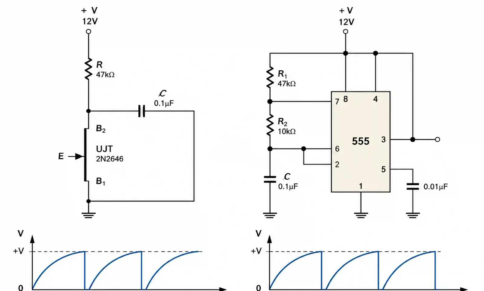
5. Design Considerations and Common Mistakes
Timing resistor range errors are the most frequent UJT design mistake. For reliable oscillation, the timing resistor must fall between R_min = (VBB - Vv) / Iv and R_max = (VBB - Vp) / Ip. Values below R_min cause latched operation; values above R_max prevent oscillation. For a 2N2646 at VBB = 12V, this yields approximately 10kΩ to 2.2MΩ.
Temperature frequency drift catches designers by surprise. UJT oscillator frequency shifts with temperature due to RBB positive coefficient (+0.8%/°C), η variation (-0.3%/°C), and timing capacitor coefficient. Net drift runs -0.2% to +0.5%/°C depending on components. Use NPO/COG ceramic capacitors to offset RBB positive coefficient, or add an NTC thermistor in series with the timing resistor for active compensation.
Output pulse loading affects pulse characteristics. Valley current rating (typically 50mA max) limits direct load impedance. For SCR triggering, verify the UJT output can source required gate trigger current plus margin. For multiple SCRs, use pulse transformers or buffer amplifiers rather than direct parallel connection.
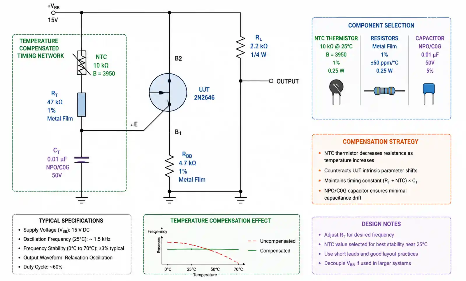
Supply voltage regulation affects both timing and pulse amplitude. Trigger point scales with VBB (Vp ≈ ηVBB + 0.7V), so ripple directly modulates frequency. Use RC/LC filtering to reduce ripple below 1% of VBB for timing-critical applications. Empirical testing under expected supply variation is necessary during validation.
6. Supply Chain and Sourcing Factors
2N2646/2N2647 series remain readily available from multiple sources with 8-16 week lead times. Specialized types like 2N4870 face limited availability (16-26 weeks). Programmable UJTs (2N6027/2N6028) maintain better availability due to educational and adjustable-timing applications.
| Component Category | Lead Time (Standard) | MOQ | Available Sources | Availability Risk |
|---|---|---|---|---|
| 2N2646/2N2647 (Standard UJT) | 8-16 weeks | 1,000-3,000 pcs | 3-5 manufacturers | Medium |
| 2N6027/2N6028 (PUT) | 6-12 weeks | 500-2,000 pcs | 2-4 manufacturers | Low-Medium |
| 2N4870/2N4871 (Low Ip) | 16-26 weeks | 2,000-5,000 pcs | 1-2 manufacturers | High |
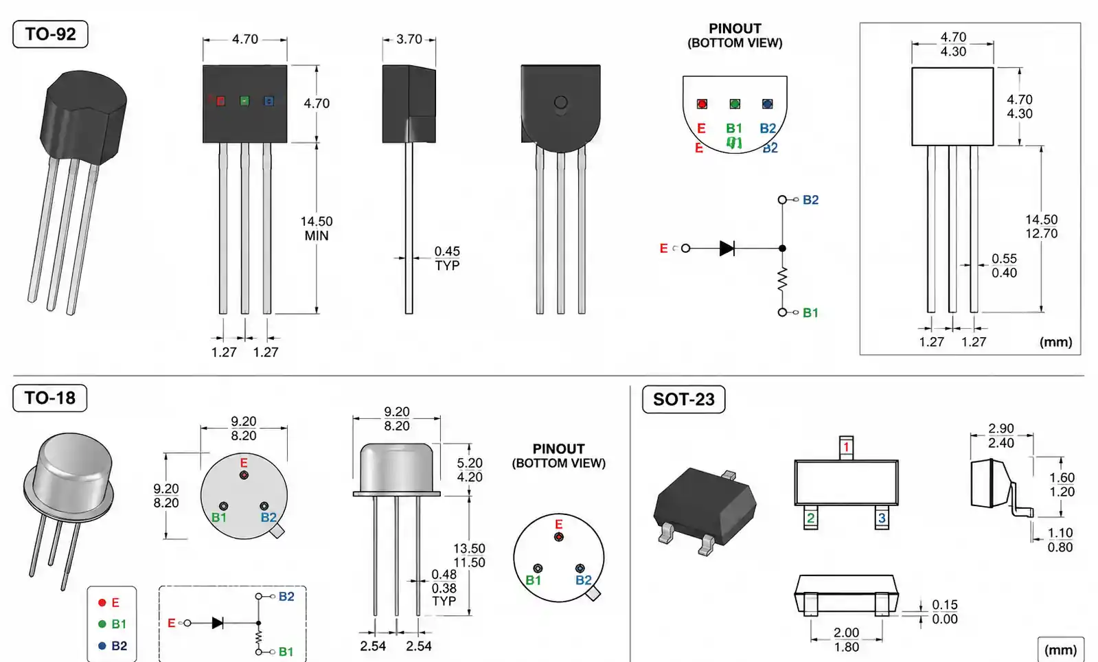
| Generic TO-92 UJTs | 10-18 weeks | 1,000-5,000 pcs | Multiple Asian suppliers | Medium |
Cross-reference options require careful parameter verification—different manufacturers' versions may exhibit different η ranges or Ip values. Qualify alternate sources across full temperature range with worst-case timing tolerances. For new designs with >10-year lifecycles or <5,000 units/year, weigh UJT supply risks against alternative timing solutions. Consider socketed layouts enabling migration to PUT alternatives if specific UJT types become unavailable.
7. FAQ
What's the difference between UJT and PUT?
A standard UJT has fixed η determined during manufacturing. A PUT uses external resistors to program the trigger point, offering adjustable characteristics and tighter tolerances. PUTs provide flexibility for field adjustment or wide frequency ranges; standard UJTs offer lower cost and simpler circuits.
Can UJTs operate above 125°C?
Standard TO-92 UJTs are rated for junction temperatures up to 125°C, limiting ambient operation to 85-100°C. For higher temperatures, consider ceramic-packaged UJTs rated to 150°C or high-temperature 555 timer variants.
How do I calculate UJT oscillator frequency?
f ≈ 1 / [RT × CT × ln(1/(1-η))]. For η = 0.63, this simplifies to approximately f ≈ 1 / (RT × CT). For precise prediction, include valley resistance and discharge time: f = 1 / [RT×CT×ln(1/(1-η)) + RB1×CT].
How to handle long lead times?
Qualify multiple cross-references during development. PUTs can substitute for standard UJTs with external resistor changes. Consider buffer stock based on annual consumption. For new designs, evaluate 555 timers or microcontroller solutions for better long-term availability.
Common failure modes and prevention?
Emitter-base junction breakdown from reverse transients—protect with Zener or TVS device rated 20-30% below maximum reverse voltage. Interbase overvoltage—add TVS on VBB supply. Thermal failures—include current limiting in trigger output paths. Validate with IEC 61000-4-4 (EFT) and IEC 61000-4-5 (surge) testing.
8. Conclusion
For continuous SCR triggering above 1 kHz or precision timing better than ±3% across temperature, prioritize PUTs with external precision resistors or 555-based timer solutions offering superior frequency stability. Standard UJTs remain optimal for cost-sensitive, moderate-accuracy timing and trigger applications below 100 Hz where minimal component count and low unit cost outweigh frequency tolerance limitations.
