


Complete Guide: How to Wire a 4-Pin and 5-Pin Relay for Automotive and Industrial Applications
Understanding relay wiring is essential for anyone working with electrical circuits, whether in automotive repair, industrial control systems, or DIY electronics projects. This comprehensive guide will walk you through everything you need to know about wiring 4-pin and 5-pin relays, from basic concepts to advanced troubleshooting techniques.
Table of Contents
- What is a Relay and How Does It Work?
- Understanding 4-Pin vs 5-Pin Relay Configurations
- Relay Pin Configuration and Terminal Layout
- Step-by-Step Guide: Wiring a 4-Pin Relay
- Step-by-Step Guide: Wiring a 5-Pin Relay
- Common Relay Applications in Automotive and Industrial Settings
- How to Test and Troubleshoot Relay Circuits
- Best Practices and Safety Tips for Relay Wiring
1. What is a Relay and How Does It Work?
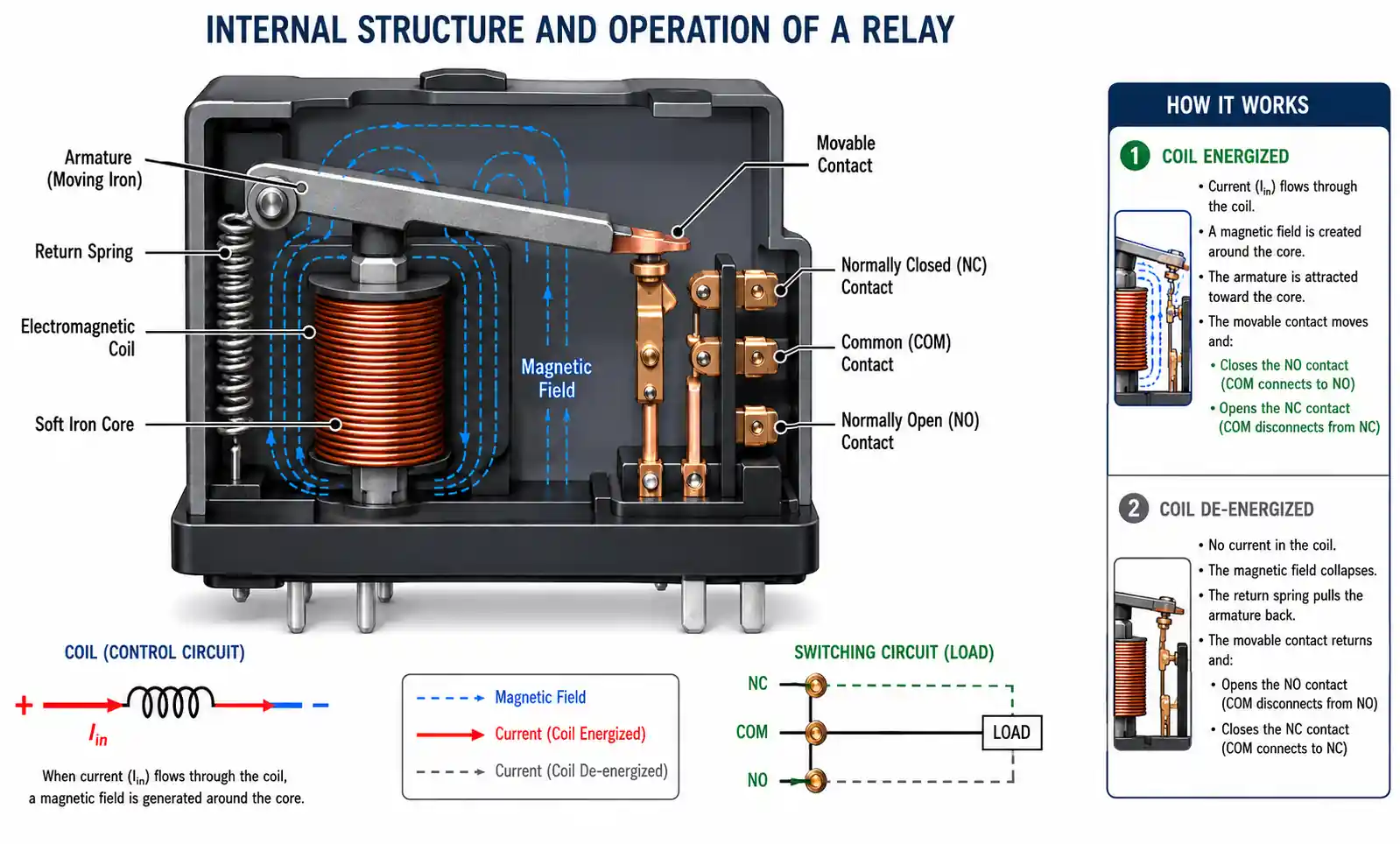
A relay is an electrically operated switch that uses a small control current to manage a much larger electrical load. Think of it as a remote-controlled switch that allows low-power circuits to control high-power devices safely and efficiently.
The fundamental principle behind relay operation involves electromagnetic induction. When current flows through the relay's coil, it creates a magnetic field that physically moves an internal switch mechanism, either closing or opening electrical contacts. This simple yet powerful design enables a wide range of applications across automotive, industrial, and residential electrical systems.
Key advantages of using relays include:
- Current amplification: Control high-current devices with low-current switches
- Electrical isolation: Separate control circuits from power circuits for enhanced safety
- Remote switching: Operate devices from a distance without running heavy-gauge wire
- Circuit protection: Prevent switch contacts from burning out when handling large loads
- Automation: Enable programmable control of electrical equipment
Modern relays have become indispensable in the automotive industry, with the global automotive relay market projected to reach USD 20.45 billion in 2026, driven by increasing vehicle electronics and electrification trends.
2. Understanding 4-Pin vs 5-Pin Relay Configurations
The primary difference between 4-pin and 5-pin relays lies in their switching capabilities and connection options. Understanding when to use each type is crucial for proper circuit design.
4-Pin Relay (SPST - Single Pole Single Throw)
A 4-pin relay provides simple on/off switching functionality. It has one output that's normally open (disconnected) and closes when the relay is energized. This configuration is ideal when you need straightforward switching without alternative circuit paths.
Common 4-pin relay uses:
- Headlight control circuits
- Electric fuel pump activation
- Horn circuits
- Cooling fan control
- Auxiliary lighting systems
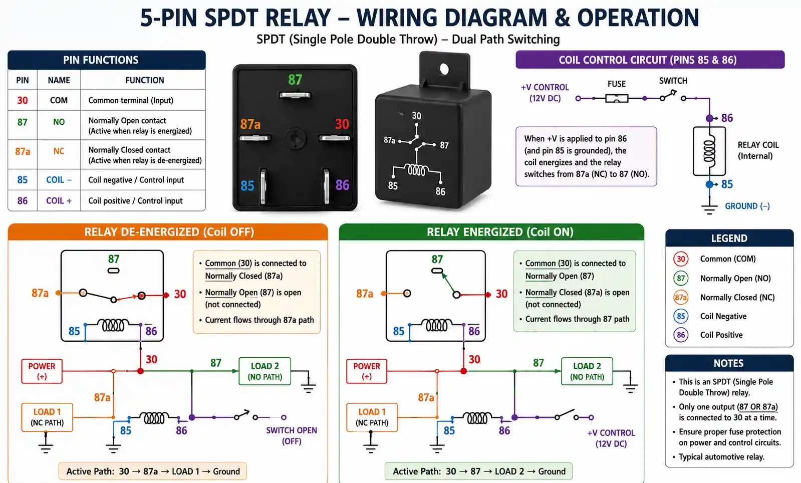
5-Pin Relay (SPDT - Single Pole Double Throw)
A 5-pin relay offers more versatility with two output terminals: one normally closed (NC) and one normally open (NO). When de-energized, current flows through the normally closed contact. When energized, the relay switches current to the normally open contact, providing dual-circuit control capability.
Common 5-pin relay applications:
- Dual-filament headlight switching (high/low beam)
- Reversing motor direction
- Backup camera power with reverse lights
- Alternating between two power sources
- DRL (Daytime Running Light) systems
Key Differences Summary:
| Feature | 4-Pin Relay | 5-Pin Relay |
|---|---|---|
| Terminals | 4 | 5 |
| Switching Type | SPST (Single Throw) | SPDT (Double Throw) |
| Default State | One circuit, normally open | Two circuits (NC and NO) |
| Applications | Simple on/off control | Circuit switching between two paths |
| Complexity | Simpler | More versatile |
3. Relay Pin Configuration and Terminal Layout
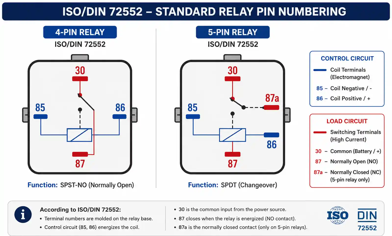
Understanding the standard pin numbering system is critical for correct relay wiring. Both 4-pin and 5-pin relays follow the ISO/DIN 72552 standardization, which ensures consistency across manufacturers.
Standard Pin Assignments:
- Pin 85: Coil ground connection (control circuit negative)
- Pin 86: Coil power connection (control circuit positive, typically from switch)
- Pin 30: Common terminal (main power input from battery or power source)
- Pin 87: Normally Open (NO) contact (power output when relay is energized)
- Pin 87a: Normally Closed (NC) contact (5-pin relays only, power output when relay is de-energized)
Understanding the Two Circuit Sides:
-
Control Circuit (Low Current): Pins 85 and 86 form the coil circuit. This is where your switch, sensor, or control module connects. Typically operates at 0.1-0.2 amps.
-
Load Circuit (High Current): Pins 30, 87, and 87a (if present) form the power switching circuit. This handles the actual device current, which can range from 10 to 40 amps depending on relay rating.
Polarity Considerations:
For standard electromechanical relays, pins 85 and 86 are interchangeable in most cases since the coil doesn't have polarity. However, relays with built-in diodes or electronic components must observe correct polarity. Always check the relay diagram printed on the relay body or consult manufacturer specifications.
4. Step-by-Step Guide: Wiring a 4-Pin Relay
Wiring a 4-pin relay correctly ensures reliable operation and prevents electrical issues. Follow this comprehensive step-by-step process for automotive or industrial applications.
Tools and Materials Needed:
- 4-pin automotive/industrial relay (rated for your load)
- Wire stripper and crimping tool
- Appropriate gauge wire (see wire sizing guide below)
- Ring or spade terminals
- Multimeter for testing
- Fuse holder and fuse (rated for load current)
- Heat shrink tubing or electrical tape
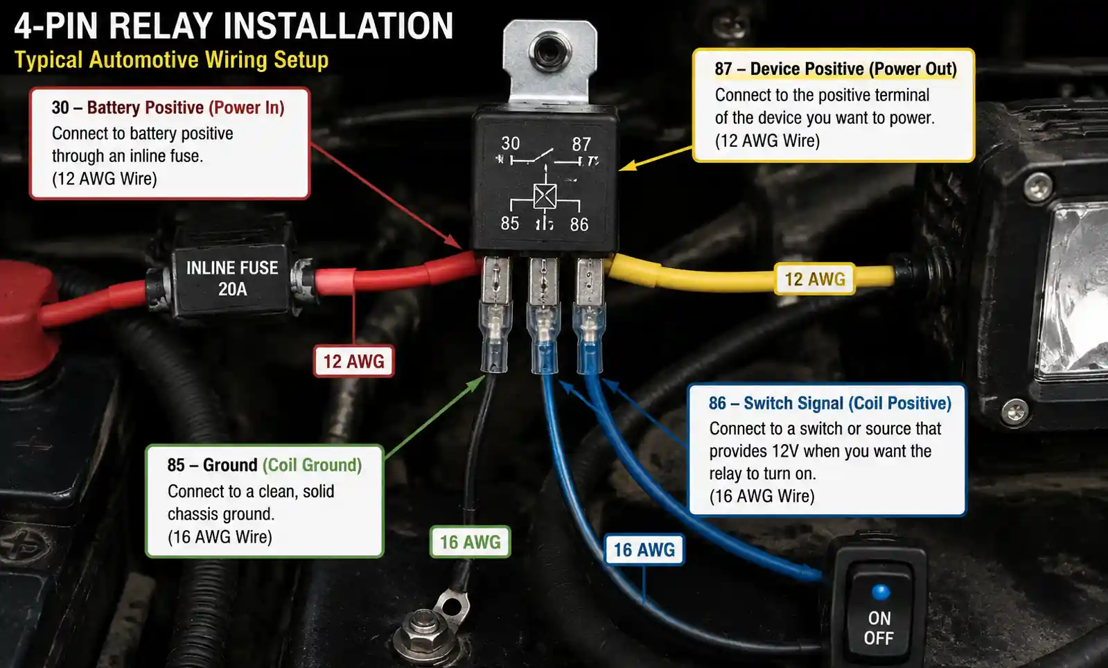
Step 1: Determine Wire Gauge Requirements
Select wire gauge based on the maximum current your device will draw:
- 10A load: Use 18 AWG minimum
- 15A load: Use 16 AWG minimum
- 20A load: Use 14 AWG minimum
- 30A load: Use 12 AWG minimum
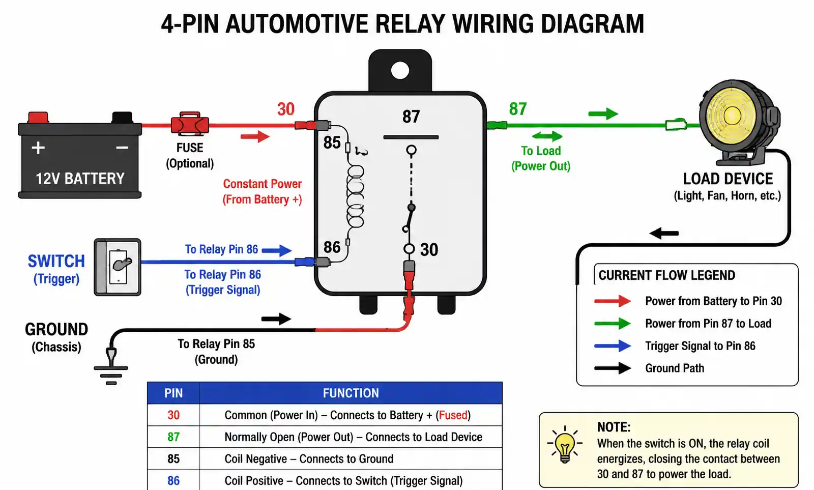
Step 2: Connect the Power Supply (Pin 30)
Connect pin 30 to your power source (typically battery positive or a fused power distribution point). This terminal should be sized for the full load current. Always install an inline fuse rated at or slightly above your device's maximum current draw, positioned as close to the power source as possible.
Step 3: Connect the Load (Pin 87)
Wire pin 87 to the positive terminal of the device you're controlling (headlights, fuel pump, fan, etc.). The device's negative terminal should connect to ground independently.
Step 4: Connect the Control Circuit Ground (Pin 85)
Connect pin 85 to a clean chassis ground or battery negative. Ensure the ground connection is solid and corrosion-free for reliable relay operation.
Step 5: Connect the Trigger Signal (Pin 86)
Wire pin 86 to your control switch, sensor, or ECU output. This low-current connection can use smaller gauge wire (typically 18-20 AWG). When this pin receives power, the relay will energize and close the connection between pins 30 and 87.
Step 6: Test the Circuit
Before final installation:
- Use a multimeter to verify no continuity between pins 30 and 87 when de-energized
- Apply power to pin 86 and verify continuity between pins 30 and 87
- Check for proper voltage at the load when relay is energized
- Listen for an audible click when the relay activates
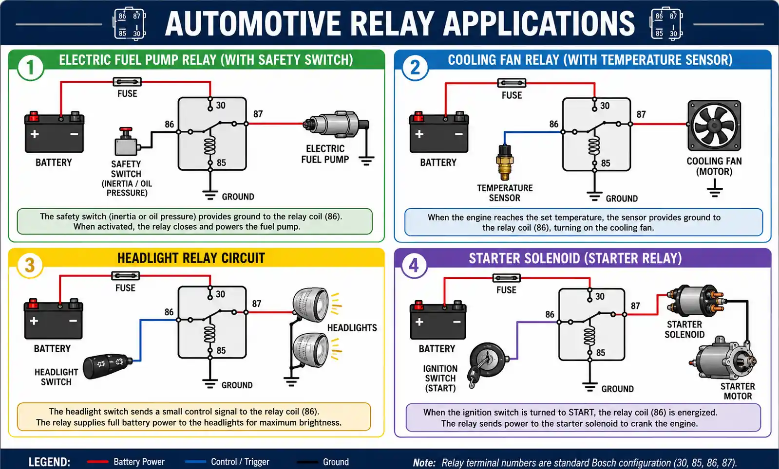
Common 4-Pin Relay Wiring Examples:
Example: Electric Fuel Pump Control
- Pin 30: Battery positive (with 15A fuse)
- Pin 87: Fuel pump positive wire
- Pin 85: Chassis ground
- Pin 86: Ignition switch or oil pressure safety switch
5. Step-by-Step Guide: Wiring a 5-Pin Relay
Five-pin relay wiring provides additional flexibility with its normally closed contact, enabling more sophisticated circuit designs and dual-path switching applications.
Step 1: Identify Your Switching Requirements
Determine which devices connect to which terminals:
- Pin 87 (NO): Device that operates when relay is energized
- Pin 87a (NC): Device that operates when relay is de-energized or as a default circuit
Step 2: Wire the Common Terminal (Pin 30)
Connect pin 30 to your main power source with appropriate fusing. This terminal supplies power to either pin 87 or 87a depending on relay state.
Step 3: Connect Both Output Terminals
- Pin 87: Wire to the device that should activate when the relay is energized
- Pin 87a: Wire to the device that should be active by default (when relay is off)
Only one device will receive power at a time. When the relay switches, power shifts from one output to the other.
Step 4: Wire the Control Circuit
- Pin 85: Connect to ground
- Pin 86: Connect to your trigger source (switch, sensor, or control module)
Step 5: Verify Proper Operation
Test both relay states:
- With relay de-energized: Verify continuity between pins 30 and 87a
- With relay energized: Verify continuity between pins 30 and 87
- Confirm proper voltage delivery to both devices in their respective states
Common 5-Pin Relay Applications:
Example: High/Low Beam Headlight Control
- Pin 30: Battery positive (with 30A fuse)
- Pin 87: High beam headlights
- Pin 87a: Low beam headlights
- Pin 85: Chassis ground
- Pin 86: High beam switch
Example: DRL (Daytime Running Light) System
- Pin 30: Battery positive
- Pin 87: Main headlights (when activated)
- Pin 87a: DRL lamps (default state)
- Pin 85: Ground
- Pin 86: Headlight switch signal
6. Common Relay Applications in Automotive and Industrial Settings
Relays serve critical functions across numerous automotive and industrial applications. Understanding these use cases helps you recognize when relay implementation is the right solution.
Automotive Applications:
-
Lighting Systems Modern vehicles extensively use relays for headlight control, fog light circuits, and auxiliary lighting. Relays prevent headlight switch contacts from burning out due to high current draw, extending switch lifespan significantly.
-
Electric Fuel Pump Control Fuel pump relays provide safe, reliable power delivery while incorporating safety interlocks. Many systems use oil pressure switches in conjunction with relays to automatically shut off fuel pumps if the engine stops running.
-
HVAC and Cooling Systems Cooling fan relays activate based on temperature sensor input, controlling high-current fan motors without overloading climate control modules. Multi-speed fan systems often employ multiple relays for different speed settings.
-
Window and Lock Actuators Power window and central locking systems use relays to protect body control modules from high actuator currents while enabling remote control functionality.
-
Starter Motor Circuits The starter solenoid functions as a heavy-duty relay, allowing the ignition switch to control the massive current required by the starter motor without routing that current through the vehicle interior.
Industrial Applications:
-
Motor Control Circuits Industrial control panels use relays to start, stop, and reverse motor operation in manufacturing equipment, conveyor systems, and automated machinery.
-
HVAC Control Systems Building automation systems employ relays for controlling heating elements, air conditioning compressors, and ventilation fans based on thermostat or BMS commands.
-
Pump and Valve Control Water treatment plants, irrigation systems, and industrial processes use relay-controlled pumps and solenoid valves for automated fluid management.
-
Safety Interlocks Machine safety systems use relays with forced-contact checking for emergency stop circuits and safety door interlocks, ensuring machinery cannot operate under unsafe conditions.
-
Lighting Control Commercial and industrial facilities use relays for centralized lighting control, allowing low-voltage control systems to manage high-current lighting loads.
7. How to Test and Troubleshoot Relay Circuits
Proper testing procedures help diagnose relay failures and circuit problems quickly and accurately. Most relay issues fall into three categories: relay failure, control circuit problems, or load circuit issues.
Tools Required for Relay Testing:
- Digital multimeter (DMM)
- Test light or power probe
- Spare relay (known good) for comparison
- Wiring diagram for your specific application
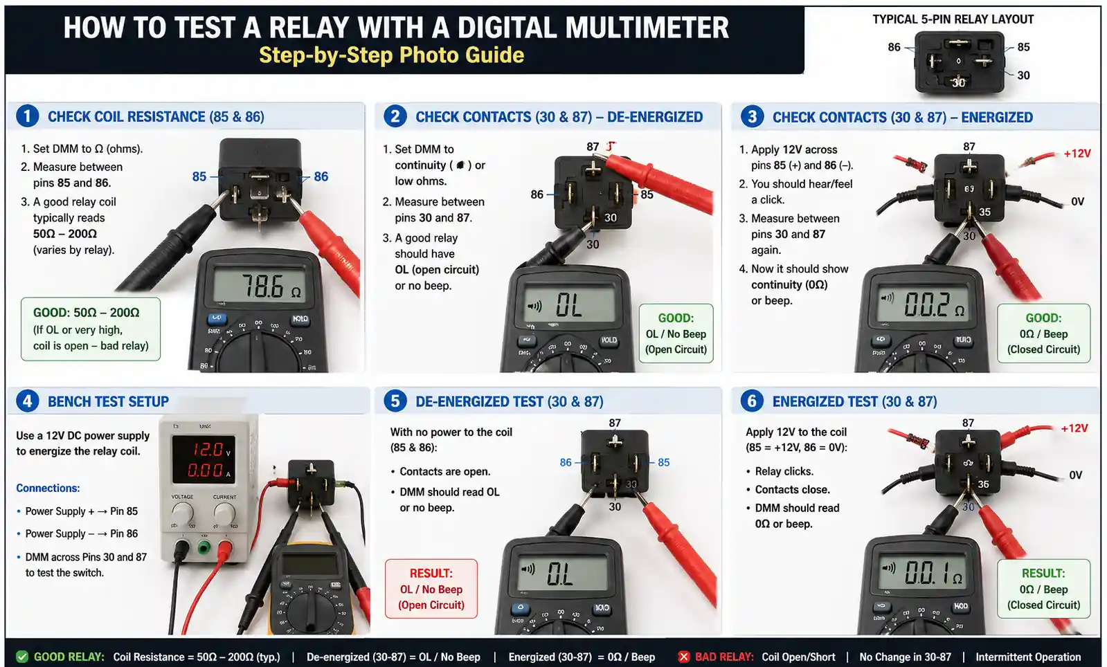
Testing a Relay Out of Circuit:
Step 1: Visual Inspection Examine the relay for physical damage, burnt terminals, or melted plastic housing. Check for corrosion on pins and inspect the relay socket for damage.
Step 2: Continuity Testing
- Set multimeter to continuity or ohms mode
- Test coil resistance between pins 85 and 86 (typical range: 50-120 ohms)
- Verify no continuity between pins 30 and 87 (with relay de-energized)
- For 5-pin relays, verify continuity between pins 30 and 87a when de-energized
Step 3: Bench Testing
- Connect pin 85 to ground
- Connect pin 86 to a 12V power source (for 12V relays)
- Listen for audible click
- Verify continuity between pins 30 and 87 while energized
- Verify continuity breaks when power is removed
Troubleshooting In-Circuit Relay Problems:
Problem: Device Won't Activate
Diagnostic Steps:
- Check for battery voltage at pin 30 (power supply)
- Check for voltage at pin 86 when triggering (control signal)
- Verify solid ground at pin 85
- Check for voltage at pin 87 when relay is energized
- Verify device ground connection
Problem: Relay Clicks But Device Doesn't Work
This indicates the control circuit is functioning but the load circuit has issues:
- Measure voltage drop between pin 30 and pin 87 with device operating
- High voltage drop (>0.5V) indicates corroded contacts or undersized relay
- Check for proper voltage at device terminals
- Verify device is functional by testing with direct power
Problem: No Click When Triggered
Check Control Circuit:
- Verify trigger voltage reaches pin 86
- Test coil resistance (should be 50-120 ohms typically)
- Confirm solid ground connection at pin 85
- Check for corroded relay socket pins
Problem: Relay Stays Energized Continuously
This dangerous condition indicates stuck contacts:
- Replace relay immediately
- Inspect for causes: excessive current, poor ventilation, or voltage spikes
- Verify load current doesn't exceed relay ratings
Using a Test Light for Quick Diagnostics:
A simple 12V test light provides fast diagnosis:
- Ground the test light clip
- Probe pin 30: Light should illuminate (confirms power supply)
- Probe pin 86 when triggering: Light should illuminate (confirms trigger signal)
- Probe pin 87: Light should illuminate when relay is energized
Advanced Testing: Voltage Drop Testing
Excessive voltage drop indicates circuit resistance problems:
- Measure voltage at battery: Note voltage
- Measure voltage at pin 30: Should be within 0.3V of battery
- Measure voltage at pin 87 (relay energized): Should equal pin 30 voltage
- Measure voltage at device: Should be within 0.5V of pin 87
Any voltage drop exceeding these values indicates poor connections, corroded terminals, or undersized wiring.
8. Best Practices and Safety Tips for Relay Wiring
Following established best practices ensures reliable, safe relay operation and prevents common problems that can lead to circuit failure or fire hazards.
Wire Sizing and Fuse Selection:
Always size wiring and fuses based on maximum expected current draw, not average current. Undersized wire generates excessive heat and voltage drop, while oversized fuses won't protect against overload conditions.
Wire Gauge Selection Guide:
- Calculate voltage drop: No more than 3% for 12V systems
- For long wire runs, increase wire gauge to compensate
- Use stranded wire for automotive applications (vibration resistance)
- Secure all wiring to prevent chafing and movement damage
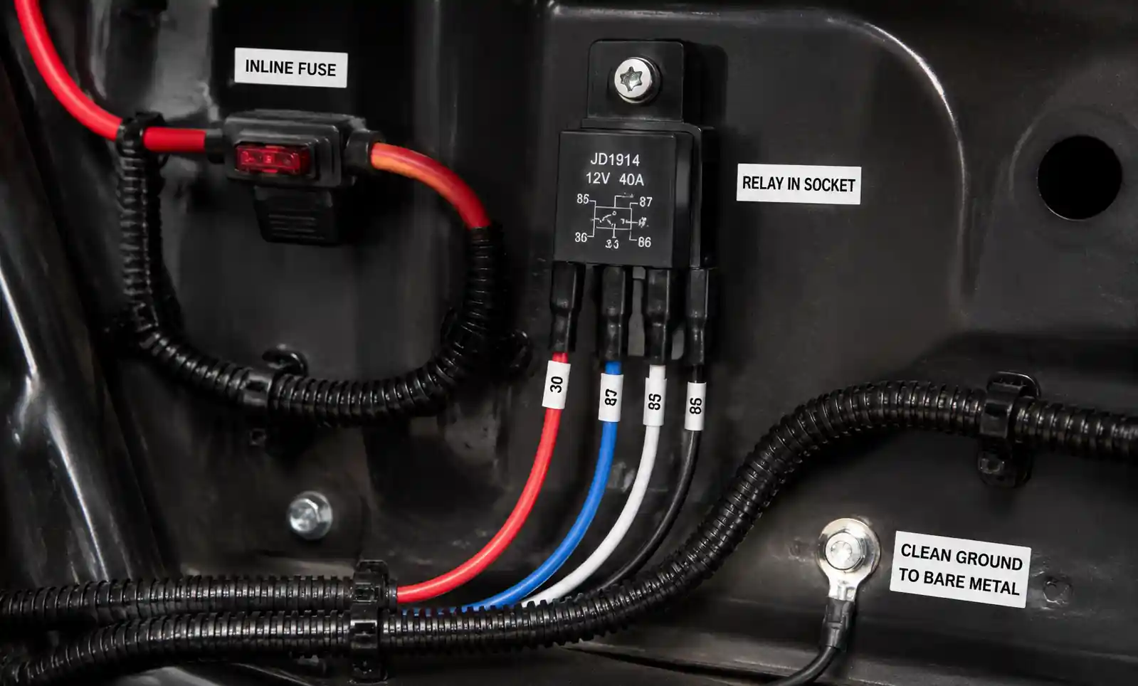
Fuse Placement:
Position fuses as close to the power source as possible, ideally within 18 inches of the battery or main power distribution point. This protects the entire wire run from shorts to ground.
Relay Protection: Flyback Diodes
When controlling inductive loads (motors, solenoids, other relay coils), install a flyback diode across pins 85 and 86. The diode prevents voltage spikes when the relay de-energizes, protecting control circuits and electronic modules from damage.
Diode orientation: Cathode (band) to pin 86, anode to pin 85.
Ground Connection Quality:
Poor grounds cause the majority of electrical problems. Follow these ground best practices:
- Use ring terminals for permanent installations
- Sand or grind mounting surfaces to bare metal
- Apply dielectric grease to prevent corrosion
- Use star washers to ensure tight electrical contact
- Never rely on paint or powder-coated surfaces for ground connections
Relay Mounting Considerations:
- Mount relays in protected locations away from water, excessive heat, and vibration
- Ensure relay orientation matches manufacturer recommendations (some relays are position-sensitive)
- Use relay sockets rather than soldering direct connections for serviceability
- Secure relay sockets to prevent vibration damage
- Allow adequate ventilation around relay for heat dissipation
Contact Current Derating:
Relay contacts must be derated for inductive loads. If a relay is rated for 30A resistive load, only use it for approximately 12A (40%) inductive load. Inductive devices include:
- Electric motors
- Solenoids and actuators
- Transformers
- Other relay coils
Documentation and Labeling:
- Label all relay positions in fuse/relay panels
- Document wire colors and functions
- Maintain wiring diagrams for future troubleshooting
- Use heat-shrink labels on individual wires in complex installations
Safety Warnings:
⚠️ Always disconnect power before working on relay circuits
⚠️ Never bypass fuses or use oversized fuses
⚠️ Don't exceed relay current ratings—relays can overheat and fail, creating fire hazards
⚠️ Use proper wire gauge—undersized wire can overheat and cause fires
⚠️ Ensure proper ventilation—relays generate heat during operation
Common Mistakes to Avoid:
- Using incorrect wire gauge: Results in voltage drop and overheating
- Omitting fuses: Eliminates circuit protection and creates fire risk
- Poor ground connections: Causes intermittent operation and voltage drop
- Exceeding current ratings: Leads to premature relay failure
- Improper relay mounting: Can cause mechanical failure in high-vibration environments
- Mixing up NO and NC contacts: Results in reverse operation on 5-pin relays
- Ignoring polarity on electronic relays: Some modern relays contain diodes requiring correct polarity
Conclusion
Understanding how to properly wire 4-pin and 5-pin relays opens up countless possibilities for controlling electrical devices safely and efficiently. Whether you're working on automotive electrical systems, industrial control panels, or DIY electronics projects, relays provide the essential capability to manage high-current loads with low-current control circuits.