


8-Pin Relay: Electrical Operation, Contact Logic, Wiring Design, and Engineering Applications
An 8-pin relay is a widely used electromechanical switching device designed for isolating and controlling multiple circuits using a low-power control signal. This article presents an engineering-focused analysis of its internal structure, operating principles, contact configurations, and wiring strategies. It also explores relay types, performance specifications, common failure modes, and practical application considerations, helping engineers design reliable and safe control systems.
Catalog
- 1. Fundamentals of 8-Pin Relays
- 2. Electromechanical Operation and Switching Principle
- 3. Internal Structure and Functional Components
- 4. Wiring Logic and Circuit Design
- 5. Relay Types and Functional Variants
- 6. Electrical Specifications and Ratings
- 7. Engineering Advantages and Limitations
- 8. 8-Pin vs 5-Pin Relay: Functional Comparison
- 9. Application Scenarios
- 10. Failure Modes and Troubleshooting
- 11. Safety and Design Best Practices
- 12. FAQ
1. Fundamentals of 8-Pin Relays
An 8-pin relay typically implements a DPDT (Double Pole Double Throw) configuration, allowing simultaneous control of two independent circuits. It consists of:
- 2 pins for the coil (control side)
- 6 pins for switching contacts (2× COM, NO, NC)
From a systems perspective, the relay acts as:
- A galvanic isolation device
- A low-power to high-power interface
- A deterministic switching element
2. Electromechanical Operation and Switching Principle
2.1 Coil Energization
Applying voltage to the coil generates a magnetic field proportional to current:
- Magnetic flux pulls the armature
- Mechanical motion changes contact states
2.2 Contact State Transition
- De-energized state → COM connected to NC
- Energized state → COM switches to NO
2.3 Dynamic Characteristics
Key timing parameters:
- Operate time: 5–15 ms
- Release time: 5–10 ms
Engineering note:
- Contact bounce must be considered in digital systems
- Snubber or debounce circuits may be required
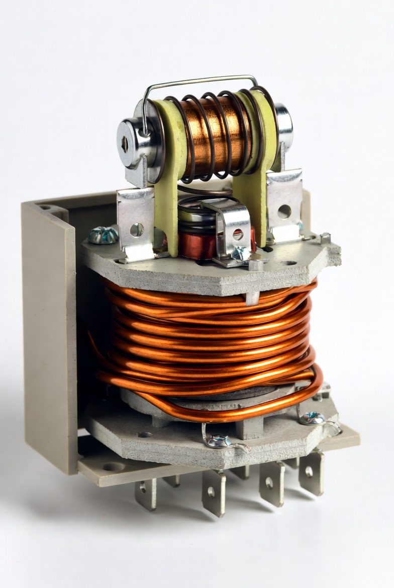
3. Internal Structure and Functional Components
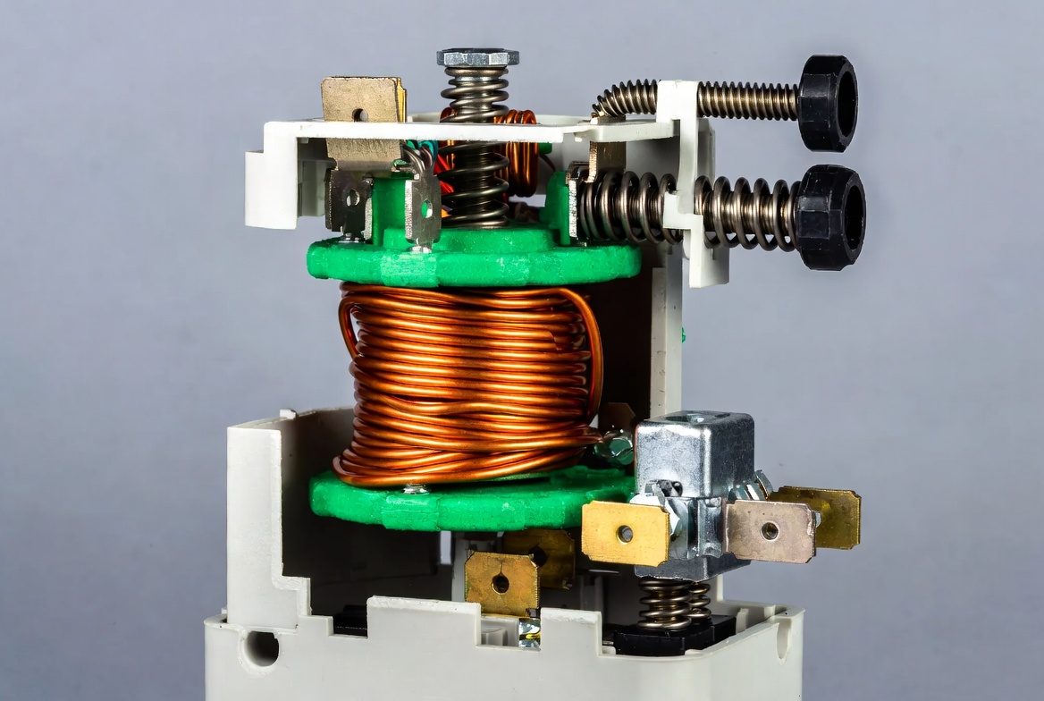
3.1 Coil and Magnetic Circuit
- Copper winding with ferromagnetic core
- Determines pull-in force and sensitivity
3.2 Armature Mechanism
- Converts magnetic force into mechanical motion
- Includes spring return system
3.3 Contact System
- Typically silver alloy contacts
- Designed for low resistance and arc resistance
3.4 Mechanical Frame and Housing
- Provides structural alignment and insulation
- Influences thermal and mechanical stability
4. Wiring Logic and Circuit Design
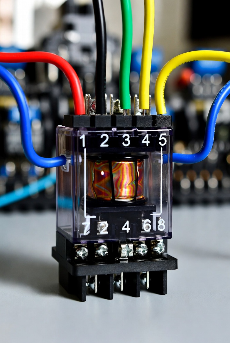
4.1 Standard Pin Configuration
Each pole includes:
- COM (common)
- NO (normally open)
- NC (normally closed)
4.2 Typical Wiring Strategies
Load Control via NO
- Load activates only when relay is energized
- Suitable for fail-safe OFF systems
Load Control via NC
- Load remains active until relay triggers
- Suitable for fail-safe ON systems
4.3 Dual-Circuit Control
DPDT enables:
- Independent switching of two circuits
- Simultaneous signal and power control
5. Relay Types and Functional Variants
5.1 Electromechanical Relay (EMR)
- Mechanical contact switching
- High isolation capability
5.2 Solid State Relay (SSR)
- Semiconductor switching
- Silent operation and long lifespan
5.3 Time Delay Relay
- Built-in timing control
- Supports delayed switching
5.4 Latching Relay
- Maintains state without continuous power
- Energy-efficient
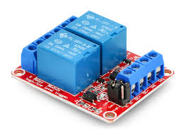
5.5 Miniature and General-Purpose Relays
- Compact and PCB-mountable
- Suitable for embedded systems
6. Electrical Specifications and Ratings
| Parameter | Typical Value |
|---|---|
| Contact Type | DPDT |
| Coil Voltage | 5V, 12V, 24V DC / 110V, 230V AC |
| Contact Rating | 5A–10A @ 250V AC |
| Pickup Voltage | 70–80% of rated voltage |
| Dropout Voltage | 10–30% of rated voltage |
| Operate Time | 5–15 ms |
| Release Time | 5–10 ms |
| Insulation Resistance | ≥ 100 MΩ |
7. Engineering Advantages and Limitations
Advantages
- Electrical isolation between control and load
- Ability to switch both AC and DC loads
- Multi-circuit switching capability
- High reliability in industrial environments
Limitations
- Mechanical wear over time
- Slower switching speed than semiconductor devices
- Contact arcing in inductive loads
8. 8-Pin vs 5-Pin Relay: Functional Comparison
| Feature | 8-Pin Relay | 5-Pin Relay |
|---|---|---|
| Contact Type | DPDT | SPDT |
| Number of Circuits | Two | One |
| Flexibility | High | Moderate |
| Application | Industrial and automation systems | Simple switching applications |
9. Application Scenarios
- Industrial automation systems
- PLC control panels
- Motor control circuits
- Lighting automation systems
- Embedded electronics and prototyping
10. Failure Modes and Troubleshooting
| Failure Mode | Root Cause | Solution |
|---|---|---|
| No switching | Coil failure or no supply voltage | Check voltage and continuity |
| Contact failure | Oxidation or wear | Replace relay |
| Overheating | Overcurrent condition | Use proper rating |
| Chattering | Unstable control signal | Stabilize power supply |
11. Safety and Design Best Practices
- Match relay ratings to application requirements
- Use flyback diodes for DC coil protection
- Add snubber circuits for inductive loads
- Ensure proper insulation and spacing
- Use relay sockets for easy maintenance
- Verify wiring before energizing
12. FAQ
Q1: Why use an 8-pin relay instead of a transistor switch?
Relays provide electrical isolation and can safely switch high voltage and current loads.
Q2: What causes relay contacts to fail?
Contact arcing, oxidation, and mechanical wear are the main causes.
Q3: Can an 8-pin relay control AC and DC loads?
Yes, as long as it is rated for the required voltage and current.
Q4: How to extend relay lifespan?
Use proper ratings, add protection circuits, and avoid excessive switching frequency.