




ADC and DAC Selection Guide for Data Acquisition Systems
Selecting the right analog-to-digital converter (ADC) and digital-to-analog converter (DAC) for data acquisition systems directly impacts measurement accuracy, system cost, and long-term reliability. Engineers designing industrial monitoring equipment, test instrumentation, or precision control systems face critical decisions about resolution, sampling rate, input configuration, and interface protocols—choices that affect both first-pass design success and production scalability. This guide addresses the core selection criteria, architecture trade-offs, and real-world design considerations that determine whether your data acquisition system meets its performance targets.
Table of Contents
- Understanding ADC and DAC Fundamentals in Data Acquisition
- Key Specifications: Resolution, Speed, and SNR
- ADC Architecture Selection: SAR vs Sigma-Delta vs Pipeline
- Multi-Channel Considerations: Multiplexed vs Simultaneous Sampling
- DAC Selection for Control and Signal Generation
- Interface Standards and System Integration
- FAQ
- Conclusion
1. Understanding ADC and DAC Fundamentals in Data Acquisition
Data acquisition systems bridge the analog and digital worlds, converting physical measurements into digital data for processing, storage, and analysis. The ADC serves as the input stage, digitizing sensor signals from thermocouples, strain gauges, accelerometers, and other transducers. The DAC provides the output stage, generating analog control signals for actuators, valve controllers, or test stimulus generation. Both converters must meet application-specific accuracy, speed, and noise requirements while operating within system constraints for power, cost, and board space.
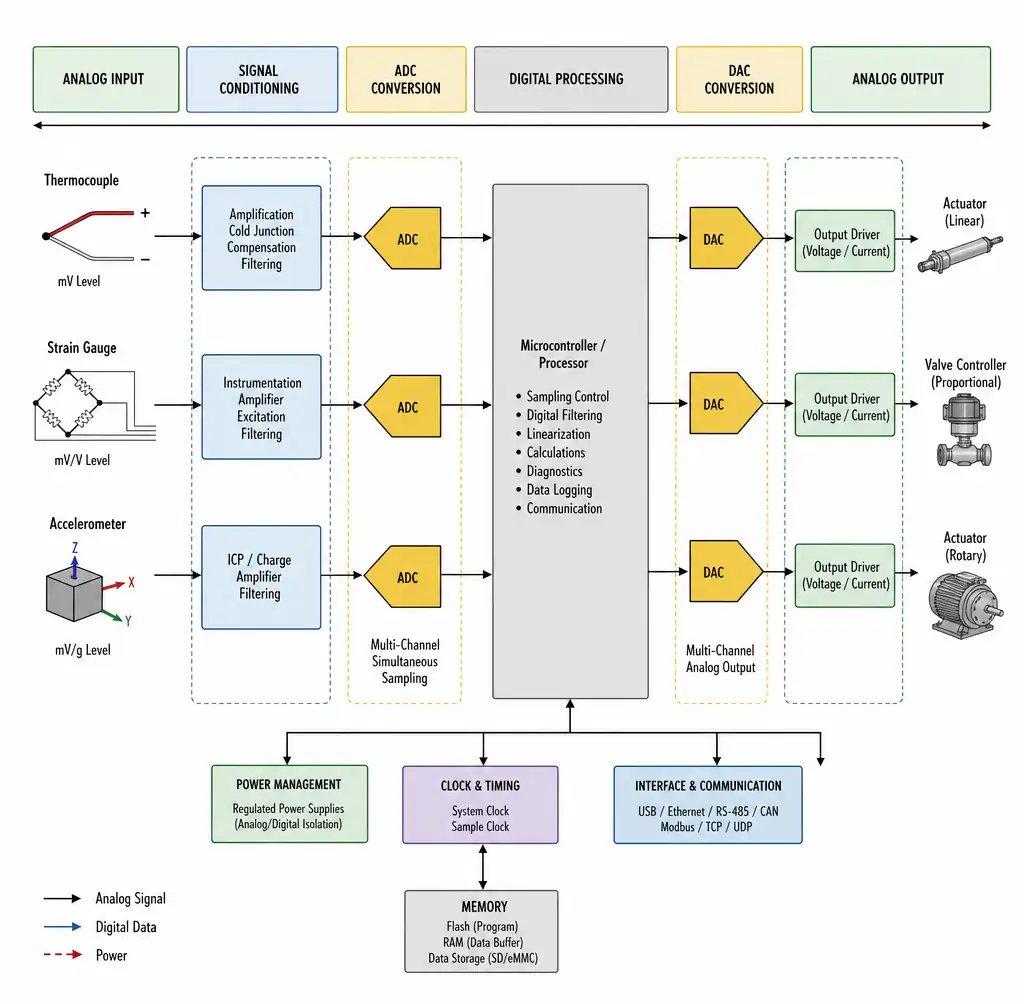 Data acquisition system block diagram showing ADC input stage and DAC output stage
The fundamental performance metric for any converter is resolution—the number of discrete digital codes available to represent the analog signal range. A 12-bit ADC divides the input range into 4,096 steps, while a 16-bit device provides 65,536 steps. However, resolution alone does not guarantee accuracy. Effective resolution depends on signal-to-noise ratio (SNR), integral nonlinearity (INL), and differential nonlinearity (DNL). An ADC's effective number of bits (ENOB) accounts for real-world noise and distortion, often falling 1 to 3 bits below the nominal resolution specification.
2. Key Specifications: Resolution, Speed, and SNR
Understanding the relationship between critical ADC and DAC specifications enables informed trade-off decisions during component selection. These parameters interact in ways that affect real-world performance beyond datasheet headlines.
| Specification | Typical Range | Impact on System Performance | Selection Priority |
|---|---|---|---|
| Resolution | 8-bit to 24-bit | Determines smallest detectable signal change; each bit adds ~6 dB dynamic range | High for precision measurement, medium for control loops |
| Sampling rate | 1 SPS to 100+ MSPS | Sets maximum signal bandwidth (Nyquist: fs/2); affects anti-aliasing requirements | High for AC signals, low for DC/slowly varying |
| SNR (Signal-to-Noise Ratio) | 60 dB to 120+ dB | Defines noise floor; theoretical SNR = 6.02N + 1.76 dB for N-bit converter | Critical for low-level signals (µV to mV range) |
| ENOB (Effective Bits) | Typically 0.5 to 2 bits below resolution | Real-world performance accounting for noise and distortion | Verify at your operating frequency and input level |
| INL (Integral Nonlinearity) | ±0.5 LSB to ±4 LSB | Maximum deviation from ideal transfer function; affects absolute accuracy | High for calibration-free precision measurement |
| DNL (Differential Nonlinearity) | ±0.1 LSB to ±1 LSB | Code-to-code step size variation; values >1 LSB cause missing codes | Critical for servo control and closed-loop systems |
| Input bandwidth | DC to 100+ MHz | Analog input frequency range before 3 dB rolloff; must exceed signal bandwidth | Match to application: DC for thermocouples, MHz for RF |
| Settling time (DAC) | 100 ns to 10 µs | Time to reach final value within specified error band after code change | Critical for waveform generation and fast control loops |
The relationship between SNR and ENOB provides insight into actual converter performance. ENOB is calculated as: ENOB = (SNR - 1.76) / 6.02. A 16-bit ADC with 90 dB SNR delivers approximately 14.7 ENOB—meaning nearly 1.3 bits are lost to noise and distortion. This gap widens at higher sampling rates, where dynamic performance limitations become more pronounced. According to Analog Devices' technical analysis, understanding ENOB at your specific operating conditions prevents costly redesigns when measured performance falls short of expectations.
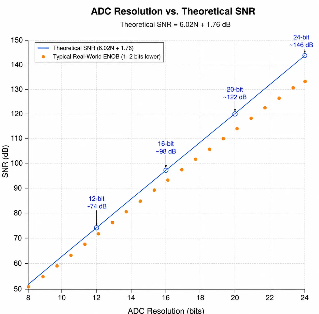 Graph showing relationship between ADC resolution and signal-to-noise ratio
3. ADC Architecture Selection: SAR vs Sigma-Delta vs Pipeline
ADC architecture fundamentally determines the speed-resolution-power trade-off space. Three primary architectures dominate data acquisition applications, each optimized for different performance profiles.
Successive approximation register (SAR) ADCs perform a binary search to converge on the input voltage value, typically completing conversion in 8 to 20 clock cycles. This architecture dominates general-purpose data acquisition because it combines moderate resolution (12 to 18 bits) with sampling rates up to several MSPS at low power consumption. SAR converters excel in multiplexed systems where multiple sensor channels share a single ADC because conversion latency is minimal—critical for applications like multi-point temperature monitoring or automated test equipment. Modern SAR ADCs achieve 16-bit resolution at 1 MSPS with ENOB exceeding 15 bits, as demonstrated in recent high-performance designs.
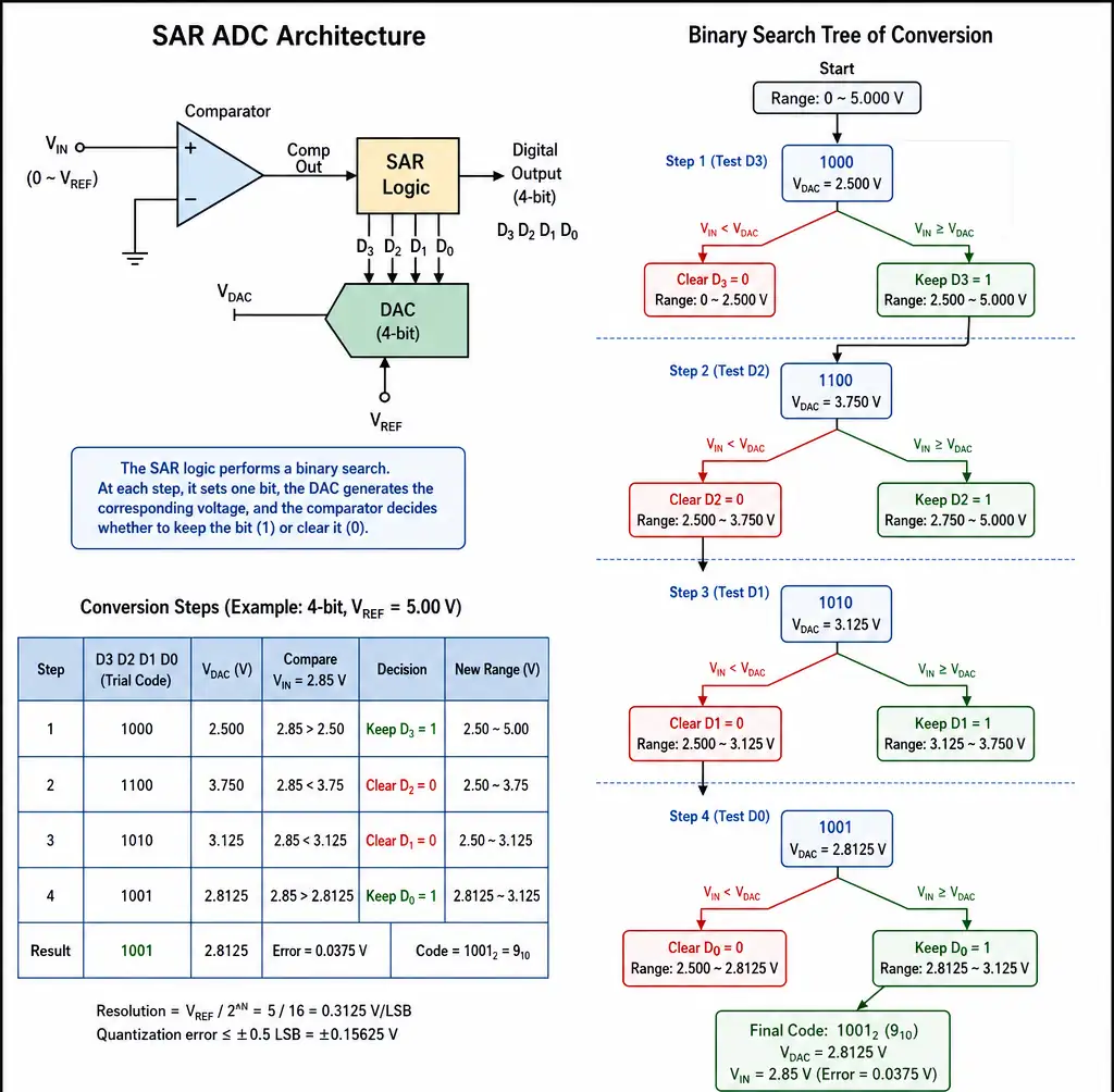 SAR ADC successive approximation conversion process diagram
Sigma-delta ADCs use oversampling and noise shaping to push quantization noise outside the signal bandwidth, then digitally filter to achieve extraordinary resolution. A 24-bit sigma-delta converter might oversample by 256x, sampling at 12.8 MHz to achieve an effective output rate of 50 kSPS. This architecture is preferred for precision industrial measurement, weigh scales, and sensor conditioning where resolution exceeds 16 bits and signal bandwidth remains below 100 kHz. The integrated digital filter provides simultaneous anti-aliasing and decimation, simplifying analog front-end design. However, filter group delay introduces latency ranging from milliseconds to hundreds of milliseconds depending on decimation ratio—unsuitable for real-time control loops requiring immediate feedback.
4. Multi-Channel Considerations: Multiplexed vs Simultaneous Sampling
Data acquisition systems frequently monitor multiple sensor inputs—temperature zones in an oven, strain gauges on a test structure, or phase currents in a motor drive. The choice between multiplexed and simultaneous sampling architectures affects channel count, system cost, phase accuracy, and overall performance.
Multiplexed systems route multiple analog inputs through a single ADC using an analog multiplexer. This approach minimizes cost and board space, as one 16-bit ADC replaces eight individual converters. Sequential sampling suffices for applications where relative timing between channels is non-critical, such as environmental monitoring where all temperatures update at 1 Hz. Channel-to-channel skew equals the per-channel conversion time—for a 1 MSPS ADC scanning 8 channels, successive samples are separated by 1 µs. This skew is negligible when signal bandwidth is below 100 Hz but becomes problematic for AC measurements or when phase relationships matter.
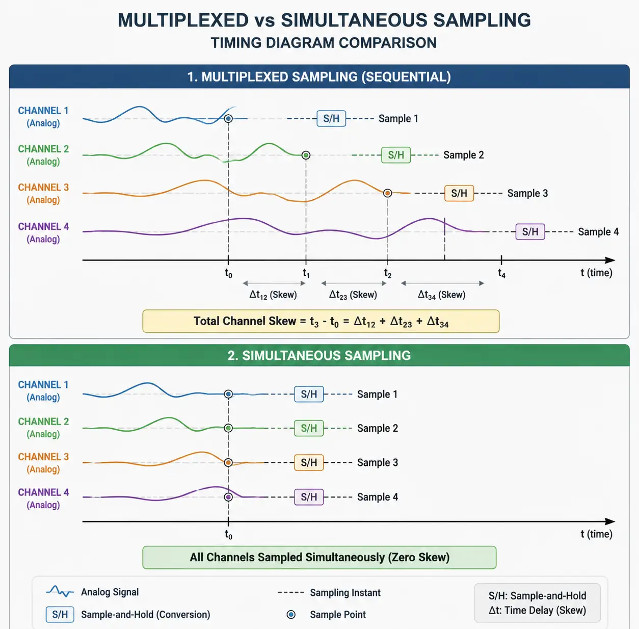 Timing diagram comparing multiplexed sequential sampling versus simultaneous sampling
Simultaneous sampling systems use dedicated ADCs for each channel, triggered by a common sample clock. All inputs are captured at precisely the same instant, preserving phase relationships critical for three-phase power measurement, vibration analysis with multiple accelerometers, or beamforming in acoustic systems. According to Analog Devices' application guidance on multichannel systems, simultaneous sampling is essential when analyzing phase information between orthogonal sensors to detect faults like imbalance, misalignment, or bearing defects in rotating machinery.
The cost trade-off is substantial: a 4-channel simultaneous sampling system requires four ADCs, four voltage references, and four sets of signal conditioning, potentially doubling or tripling BOM cost compared to a multiplexed approach. However, this investment becomes justified in applications where:
- Phase accuracy between channels must be maintained (power quality analysis, motor control)
- Input signals change rapidly relative to multiplexer settling time (vibration monitoring above 1 kHz per channel)
- Channel crosstalk must be minimized (precision measurement where one channel cannot disturb others)
- Real-time triggering across all channels is required (fault detection systems)
Industrial three-phase power monitoring exemplifies where architecture choice matters. Accurate power and energy calculations require simultaneous measurement of voltage and current waveforms across all three phases. Sequential sampling introduces phase errors that corrupt power factor calculations and harmonic analysis. High-performance systems for advanced powerline monitoring leverage simultaneous-sampling ADCs specifically designed for this application, achieving better than 0.1° phase matching across channels.
5. DAC Selection for Control and Signal Generation
While ADCs receive more attention in data acquisition discussions, DACs play equally critical roles in control loop outputs, calibration signal generation, and setpoint adjustment. DAC selection criteria differ from ADC requirements because the application focus shifts from measurement to signal generation and control.
Control loop applications prioritize settling time and update rate. A closed-loop temperature controller adjusting heater power at 10 Hz can use a sigma-delta DAC with 10 µs settling time, but a servo motor drive updating at 10 kHz requires a resistor-string or segmented DAC settling within 1 µs. Settling time specifications are defined to a specific error band (typically 0.5 LSB or 1 LSB), and the settling behavior—monotonic vs with overshoot—affects control stability.
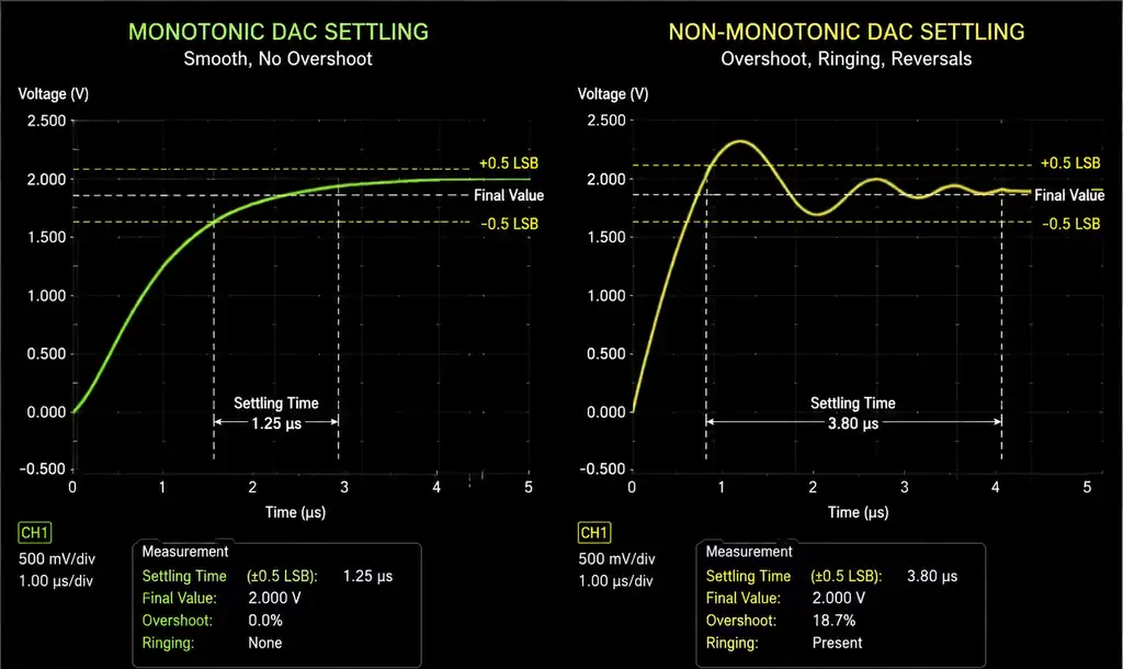 DAC settling time waveforms showing monotonic versus non-monotonic behavior
Monotonicity is critical for control applications. A monotonic DAC guarantees that increasing digital codes produce increasing (or at least non-decreasing) output voltages. Non-monotonic DACs can cause limit cycles or instability in feedback systems. All output codes must be present—no missing codes—which requires DNL < 1 LSB across the full temperature range. This matters when the DAC drives a valve actuator or motor controller where reversals in output direction could cause hunting or oscillation.
6. Interface Standards and System Integration
Digital interface selection impacts board layout complexity, processor loading, and data throughput. Modern data acquisition ADCs and DACs support serial and parallel interfaces with varying trade-offs.
SPI (Serial Peripheral Interface) dominates low-to-moderate speed data acquisition, offering simple 4-wire connections (MOSI, MISO, SCK, CS) with clock rates typically from 1 MHz to 50 MHz. A 16-bit ADC sampled at 1 MSPS requires 16 MCLK cycles per conversion plus overhead, easily accommodated by 20 MHz SPI. Multiple devices share the bus with individual chip selects, minimizing pin count. SPI lacks built-in error checking, so critical applications implement CRC validation in firmware. Daisy-chain configurations cascade multiple converters on a single SPI bus, useful in high-channel-count systems but increasing latency.
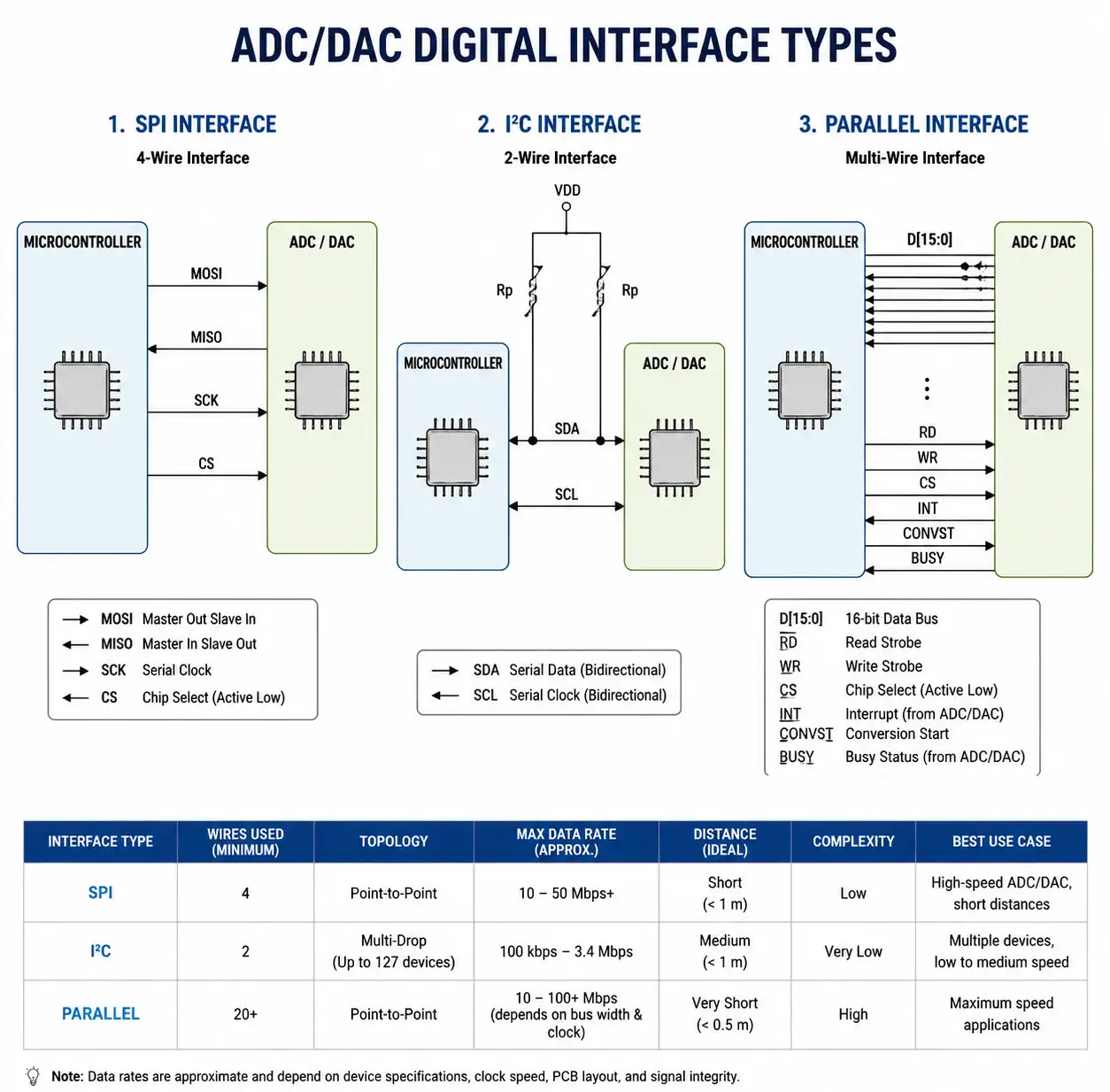 Digital interface comparison showing SPI, I2C, and parallel connections
Parallel interfaces provide maximum throughput for high-speed applications, transferring 8, 12, or 16 bits simultaneously plus control signals (read, write, chip select). A parallel 16-bit ADC updates at 10 MSPS requires only 16 data lines and control logic, achieving latencies under 100 ns. The trade-off is board real estate—parallel interfaces consume 20+ pins versus 4 for SPI. Modern high-speed ADCs often include LVDS (Low-Voltage Differential Signaling) parallel outputs, reducing EMI and enabling longer trace lengths compared to single-ended parallel buses.
System-level considerations include processor DMA (Direct Memory Access) capability for high-throughput acquisition without burdening the CPU, isolation requirements for industrial environments (isolated SPI transceivers or optocouplers), and power supply sequencing to prevent latch-up. Multi-board systems benefit from daisy-chain or multi-drop topologies that minimize interconnect complexity, while safety-critical applications may require dual-redundant acquisition paths with independent converters and voting logic.
7. FAQ
What resolution ADC do I need for my measurement application?
Resolution requirements stem from measurement uncertainty budgets. Calculate the smallest signal change you must detect, then ensure it represents at least 3 to 5 LSBs to avoid quantization noise dominating the measurement. For a 0-10V range needing 1 mV resolution, a 12-bit ADC (10V / 4096 = 2.44 mV/LSB) provides insufficient granularity—select 14-bit (0.61 mV/LSB) or 16-bit (0.15 mV/LSB) instead. Account for temperature drift, reference error, and INL that consume effective bits. A 16-bit ADC with ±4 LSB INL effectively behaves as 14-bit for absolute accuracy despite maintaining 16-bit resolution.
What is the difference between multiplexed and simultaneous sampling, and when do I need simultaneous?
Multiplexed systems sequentially sample each channel through a single ADC, introducing time skew between channels equal to the per-channel conversion time. This is acceptable when signals change slowly or phase relationships don't matter (environmental monitoring, battery voltage tracking). Simultaneous sampling captures all channels at precisely the same instant using synchronized ADCs, preserving phase information critical for power analysis, vibration diagnosis with multiple accelerometers, or acoustic beamforming. If your application requires calculating phase angle, power factor, or comparing waveform timing across channels, simultaneous sampling is essential.
What interface should I choose: SPI, I²C, or parallel?
Interface selection depends on data throughput requirements, processor capabilities, and board space constraints. SPI supports moderate-speed data acquisition (10 kSPS to 1 MSPS per ADC) with simple 4-wire connections and is compatible with most microcontrollers. I²C is ideal for configuration and slow monitoring (<10 kSPS) where minimizing pin count is paramount. Parallel interfaces are necessary for high-speed systems (>10 MSPS) where serial bus bandwidth becomes limiting, accepting the trade-off of 16 to 20 pins per device. Evaluate whether your processor supports DMA for the chosen interface to offload data movement from CPU execution.
What DAC settling time do I need for my control application?
Settling time requirements derive from control loop update rates and stability margins. A control loop updating at 1 kHz requires DAC settling within 1 ms (and preferably 100 µs to allow control algorithm execution time). Specify settling time to the accuracy band that matters—a 12-bit DAC settling to ±1 LSB is faster than settling to ±0.5 LSB. Evaluate whether overshoot is acceptable; some applications tolerate ringing as long as the output eventually settles, while others (valve control, motor drives) require monotonic settling to prevent hunting. Always verify settling time at your operating temperature and load conditions, not just typical datasheet values at 25°C with ideal loads.
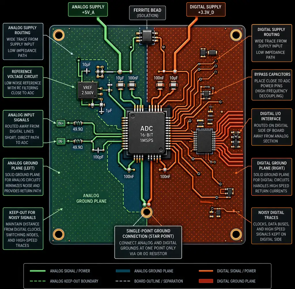 PCB layout showing proper grounding and power routing for data acquisition systems
8. Conclusion
Successful ADC and DAC selection for data acquisition systems begins with clearly defining measurement accuracy, signal bandwidth, and channel count requirements before browsing parametric tables. For precision applications measuring DC or low-frequency signals, sigma-delta ADCs deliver the highest resolution at the cost of conversion latency, while SAR architectures balance resolution up to 18 bits with sampling rates reaching several MSPS for general-purpose data acquisition. When phase relationships between multiple channels matter—power monitoring, vibration analysis, or motor control—simultaneous sampling architectures justify the additional cost through improved measurement fidelity.
