




CAN Bus Transceiver Selection for Automotive and Industrial Networks
Selecting the right CAN bus transceiver determines network reliability, data throughput, and system longevity in automotive and industrial applications. Modern CAN transceivers support speeds from 125 kbps to 8 Mbps (CAN FD), operating temperatures from -40°C to +150°C (AEC-Q100 Grade 0), and fault protection features including ±80V bus line protection and thermal shutdown. The key decision factors are protocol compatibility (classic CAN vs CAN FD), speed ratings (1 Mbps vs 5 Mbps), automotive qualification (AEC-Q100), EMC performance, standby power consumption, and bus loading capacity (up to 112 unit loads per network).
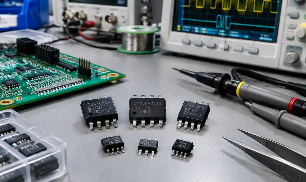 CAN bus transceiver selection criteria for automotive and industrial applications
Table of Contents
- What is a CAN Bus Transceiver?
- CAN FD vs Classic CAN Transceivers
- Transceiver Speed Ratings and Network Design
- Fault Protection Features
- Standby Modes and Power Management
- EMC Performance and Signal Integrity
- Automotive Qualification: AEC-Q100
- Bus Loading and Node Count
- Leading CAN Transceiver Families
- Selection Criteria Summary
- FAQs
- Conclusion
What is a CAN Bus Transceiver?
A CAN bus transceiver is a physical layer device that converts logic-level signals from a CAN controller into differential voltage signals on the CAN_H and CAN_L bus lines. The transceiver implements the ISO 11898-2 physical layer specification, handling signal transmission, reception, and bus arbitration.
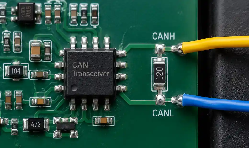 CAN transceiver physical layer implementation with CANH and CANL differential signaling
You can think of the transceiver as the interface between your microcontroller's CAN controller (which handles protocol and message framing) and the physical two-wire bus (which carries differential signals across the network). The transceiver must provide sufficient drive strength to overcome bus capacitance, handle common-mode voltage fluctuations, and protect downstream circuitry from electrical faults.
For automotive electronics and industrial automation systems, the transceiver's robustness directly impacts system uptime and safety compliance.
CAN FD vs Classic CAN Transceivers
The choice between CAN FD (Flexible Data Rate) and classic CAN transceivers affects throughput, future compatibility, and component availability. CAN FD was developed by Bosch in 2012 to address the limitations of classic CAN's 1 Mbps ceiling and 8-byte payload.
Key Technical Differences
| Parameter | Classic CAN | CAN FD |
|---|---|---|
| Max Bit Rate (Arbitration) | 1 Mbps | 1 Mbps |
| Max Bit Rate (Data Phase) | 1 Mbps | 5-8 Mbps |
| Max Payload per Frame | 8 bytes | 64 bytes |
| Frame Efficiency | Lower (overhead dominates) | Higher (8x payload) |
| Backward Compatibility | CAN 2.0A/B only | Can coexist with classic CAN nodes |
| Transceiver Requirements | Standard drive strength | Enhanced slew rate control for data phase |
According to migration studies, CAN FD reduces bus utilization by up to 60% for high-data-rate applications such as ADAS sensor fusion, battery management systems, and industrial motion control.
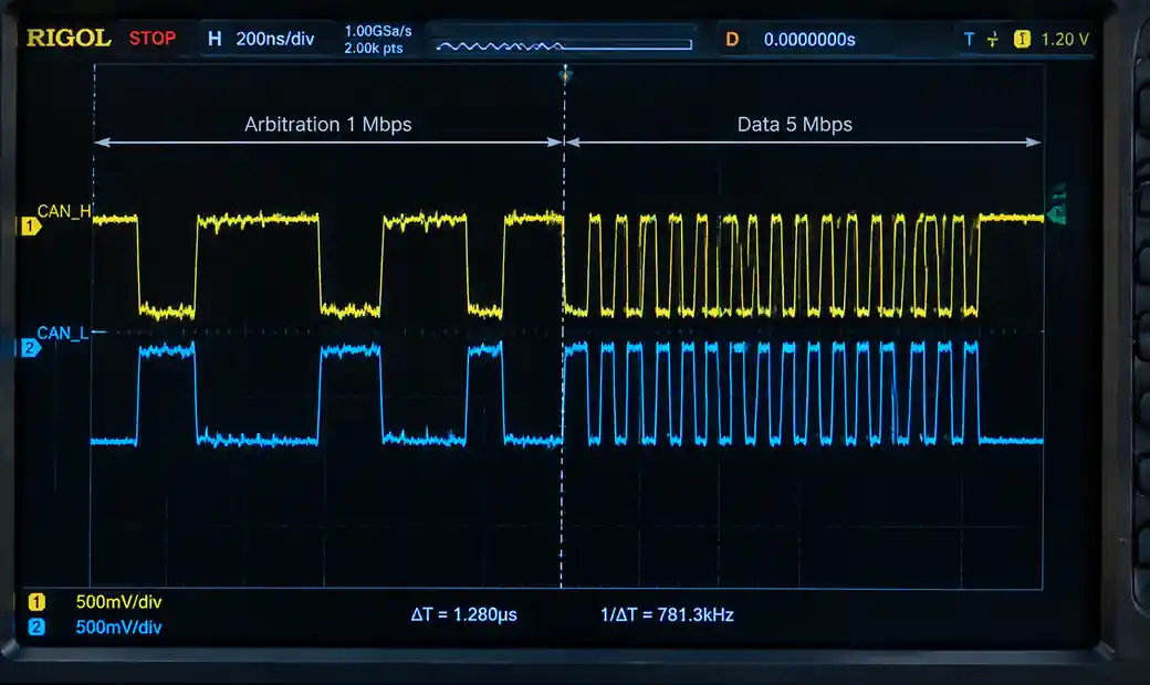 CAN FD flexible data rate waveform showing arbitration and data phase timing
When to Choose CAN FD
You should specify CAN FD transceivers when:
- Payload requirements exceed 8 bytes regularly (diagnostic logs, sensor arrays, firmware updates)
- Bus utilization approaches 80% with classic CAN
- Future system scalability is critical
- Component lifecycle extends beyond 2028 (classic-only transceivers face obsolescence risk)
Modern CAN FD transceivers like the NXP TJA1057 and Texas Instruments TCAN1044A-Q1 support both protocols, eliminating the need to stock separate components for mixed networks.
Transceiver Speed Ratings and Network Design
CAN transceiver speed ratings determine maximum bus length, node count, and signal integrity margin. ISO 11898-2 specifies propagation delay, rise time, and symmetry requirements that constrain network topology.
Speed vs Distance Trade-offs
| Bit Rate | Max Bus Length | Typical Application |
|---|---|---|
| 125 kbps | 500 m | Heavy machinery, agricultural vehicles |
| 250 kbps | 250 m | Commercial vehicles, industrial sensors |
| 500 kbps | 100 m | Passenger automotive body control |
| 1 Mbps | 40 m | Engine control, transmission, ADAS |
| 5 Mbps (CAN FD data phase) | 15-20 m | High-speed gateways, ECU flashing |
The propagation delay budget for a 1 Mbps network is approximately 1000 ns round-trip. Bus loading calculations must account for transceiver delays (typically 120-250 ns), cable propagation (5 ns/m for twisted pair), and controller sampling point configuration.
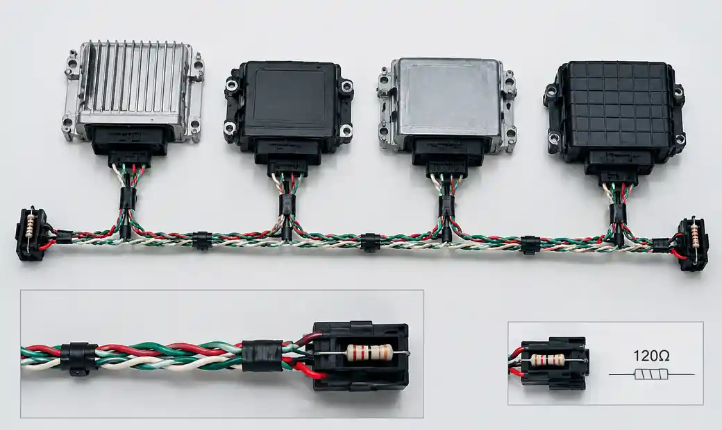 CAN bus network topology showing multiple nodes and termination resistors
For industrial installations exceeding 100 meters, you can use 250 kbps or 125 kbps with repeaters at segment boundaries. Automotive networks typically run at 500 kbps for body electronics and 1 Mbps for powertrain due to the short harness lengths within a vehicle.
Fault Protection Features
Modern CAN transceivers integrate protection circuits that prevent single-point failures from disabling the entire network. Fault-protected transceivers handle short circuits, overvoltage transients, electrostatic discharge (ESD), and thermal overload without propagating faults to the microcontroller.
Critical Protection Mechanisms
Extended Voltage Range: Industrial and automotive environments expose bus lines to battery voltage fluctuations, load dump transients, and accidental shorts to power rails. Transceivers like the Analog Devices MAX3054 tolerate ±80V on CANH and CANL pins without damage.
Thermal Shutdown: When junction temperature exceeds 150-170°C due to sustained short-circuit current, the transceiver disables its output drivers and enters a high-impedance state. This prevents thermal runaway and allows the network to continue operating with the faulted node isolated.
Unpowered Node Behavior: A transceiver whose power supply fails must not load the bus and disrupt communication among healthy nodes. Third-generation devices implement high-impedance bus pins when VCC drops below the undervoltage lockout threshold (typically 2.5-3.0V).
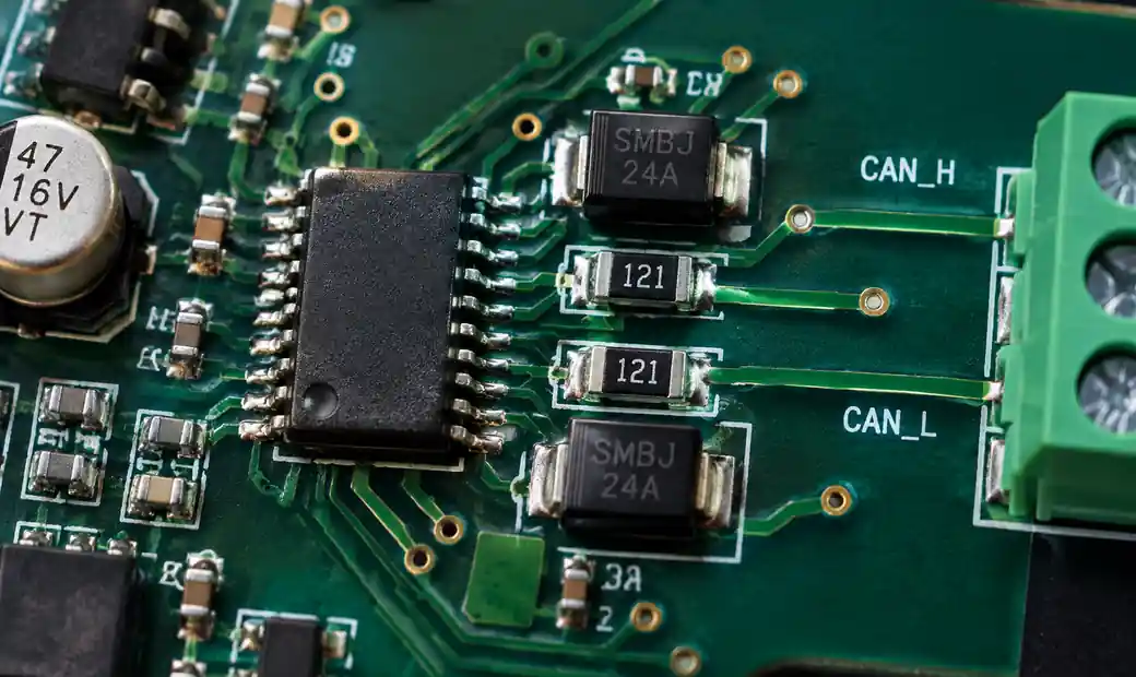 CAN transceiver fault protection features including ESD and overvoltage protection
Dominant Timeout: Some transceivers include a watchdog that detects a stuck-dominant fault (where CANH-CANL remains differential for longer than the maximum frame time) and automatically switches to recessive to allow error recovery.
For safety-critical applications compliant with ISO 26262 or IEC 61508, fault protection features contribute to achieving target ASIL (Automotive Safety Integrity Level) or SIL (Safety Integrity Level) ratings by reducing common-cause failure modes.
Standby Modes and Power Management
Power consumption matters for battery-powered nodes, always-on gateway ECUs, and systems subject to regulatory sleep-current limits. CAN transceivers typically offer multiple operating modes with current consumption ranging from 5 mA (normal) to <5 µA (shutdown).
Operating Mode Comparison
| Mode | Supply Current | Bus Monitoring | Wake-up Source |
|---|---|---|---|
| Normal | 3-10 mA | Full TX/RX | N/A |
| Standby/Listen-Only | 100-500 µA | RX wake detection | Bus activity, mode pin |
| Sleep | 10-50 µA | Limited wake detection | Mode pin, timed wake |
| Shutdown | <5 µA | None | Mode pin only |
The NXP TJA1044 achieves <12 µA in standby while retaining the ability to wake on bus activity. This enables partial networking architectures where gateway ECUs remain in standby and wake only when receiving relevant messages.
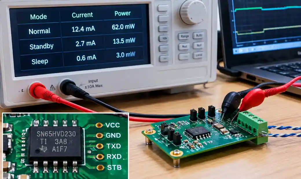 CAN transceiver power management modes and standby current consumption
You should evaluate standby current at maximum operating temperature and worst-case VCC, as leakage current increases exponentially with junction temperature. For systems targeting <50 µA total quiescent draw, the transceiver contribution must stay below 10-15 µA to leave margin for the microcontroller and voltage regulators.
Remote wake-up capability allows a sleeping node to detect a specific wake pattern on the bus (defined by the CAN controller's wake filter) and return to normal operation within 50-100 µs. This feature is mandatory for automotive partial networking per ISO 11898-6.
EMC Performance and Signal Integrity
Electromagnetic compatibility determines whether your CAN network passes radiated and conducted emission tests (CISPR 25, ISO 11452) and operates reliably in electrically noisy environments. Third-generation transceivers improve EMC through controlled slew rate, symmetrical signal paths, and integrated common-mode filtering.
EMC Design Considerations
Slew Rate Control: Fast edges (high dv/dt) generate high-frequency harmonics that radiate from the bus cable. Transceivers with programmable or adaptive slew rate (typically 20-40 V/µs) balance signal integrity against emission compliance. The NXP TJA1057 provides excellent EMC performance even without external common-mode chokes.
Symmetry: Asymmetry between CANH and CANL transitions creates differential-mode emissions. High-quality transceivers maintain <±5% edge symmetry across temperature and supply voltage.
ESD Protection: IEC 61000-4-2 Level 4 requires ±8 kV contact discharge and ±15 kV air discharge immunity on bus pins. Automotive transceivers typically specify ±8 kV contact / ±10 kV air without external protection components.
For industrial IoT sensor networks, you should verify EMC performance in the installed cable configuration, as stub lengths, shield termination, and connector types significantly affect radiated emissions above 100 MHz.
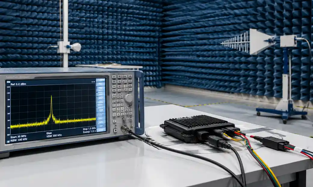 CAN transceiver EMC testing setup for radiated emissions and immunity
Automotive Qualification: AEC-Q100
The AEC-Q100 standard defines stress test qualification for integrated circuits used in automotive applications. Established in 1994 by Chrysler, Ford, and General Motors, AEC-Q100 replaces fragmented OEM-specific qualification programs with a common failure-mechanism-based test suite.
Temperature Grades
| Grade | Operating Range | Typical Mounting Location |
|---|---|---|
| Grade 0 | -40°C to +150°C | Engine compartment, transmission |
| Grade 1 | -40°C to +125°C | Passenger cabin, dashboard |
| Grade 2 | -40°C to +105°C | Trunk, cargo area |
| Grade 3 | -40°C to +85°C | Non-automotive industrial |
Most automotive CAN transceivers qualify to Grade 1 (-40°C to +125°C), which covers >95% of automotive use cases. Grade 0 parts command a 20-40% price premium and are specified only for under-hood ECUs with direct exposure to engine heat.
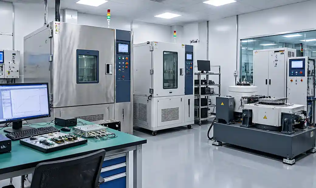 Automotive AEC-Q100 qualification testing for CAN transceivers showing temperature chambers
Qualification Test Groups
AEC-Q100 Rev-H includes:
- Group A: Accelerated environmental stress (temperature cycling, high-temperature operating life)
- Group B: Accelerated lifetime simulation (HTOL with bias, early life failure rate)
- Group C: Package assembly integrity (wire bond shear, die adhesion, moisture sensitivity level)
- Group D: Defect screening (electrical distribution, ESD, latchup)
When sourcing CAN transceivers for automotive projects, verify AEC-Q100 qualification reports through your authorized distributor rather than relying solely on datasheet claims. Counterfeit or improperly handled devices may lack the reliability margins necessary for the 15-year / 200,000 km automotive lifecycle.
Bus Loading and Node Count
CAN network capacity depends on the number of nodes, message priority structure, and bus utilization. Each transceiver contributes input capacitance and resistive loading that affects signal quality and maximum node count.
Unit Load Specifications
Classic CAN transceivers are rated at 1 unit load (1UL), limiting a single bus segment to 32 nodes. Modern fractional-load transceivers (1/8 UL or 1/4 UL) support up to 112 unit loads per network, enabling 112 nodes with 1 UL devices or 224-448 nodes with fractional-load devices.
The input impedance specification (typically 10-50 kΩ differential) determines DC loading, while input capacitance (10-50 pF) affects AC signal integrity at high bit rates. For networks with >64 nodes, you should verify signal eye diagrams at the farthest node to ensure adequate noise margin.
Bus Utilization Guidelines
Maintaining bus utilization below 80% ensures deterministic message delivery even during burst traffic conditions. At 500 kbps with 50% periodic messages and 50% event-driven messages, a well-designed network handles:
- 100-150 messages/second with 8-byte payloads (classic CAN)
- 300-400 messages/second with 64-byte payloads (CAN FD)
For mission-critical applications requiring guaranteed worst-case latency, you should perform schedulability analysis using tools that account for message arbitration, bit stuffing overhead, and error frame recovery time.
Leading CAN Transceiver Families
NXP TJA105x Series
The TJA1050 established the baseline for high-speed CAN transceivers in the early 2000s. Third-generation devices like the TJA1051 and TJA1057 improve EMC performance, add standby modes, and support CAN FD. The TJA1057 is optimized for 12V automotive applications with integrated protection and low emission.
Texas Instruments TCAN Series
The TCAN1044A-Q1 and TCAN3414 families integrate fault protection (±70V bus pins), ultra-low standby current (<12 µA), and AEC-Q100 Grade 1 qualification. These transceivers target automotive power management and battery-powered industrial systems.
Microchip MCP2551/2561
The MCP2551 remains popular for cost-sensitive industrial applications, though it lacks the fault protection and low-power modes found in newer designs. The MCP2561 adds standby functionality while maintaining pin compatibility with the MCP2551.
Analog Devices ADM3051/3052
Analog Devices specializes in isolated CAN transceivers with integrated galvanic isolation (2.5 kV or 5 kV), eliminating the need for external isolation transformers or optocouplers in high-voltage industrial environments.
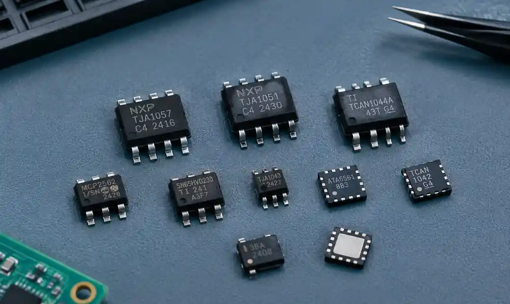 CAN transceiver product families from major manufacturers showing various package types
When evaluating manufacturers and part numbers, prioritize transceivers with active production status, broad distributor availability, and long-term supply commitments. Component obsolescence forces costly redesigns and requalification, especially for products with 10-15 year lifecycles.
CAN transceiver product families from major manufacturers showing various package types
When evaluating manufacturers and part numbers, prioritize transceivers with active production status, broad distributor availability, and long-term supply commitments. Component obsolescence forces costly redesigns and requalification, especially for products with 10-15 year lifecycles.
Selection Criteria Summary
| Criterion | Questions to Answer | Key Specifications |
|---|---|---|
| Protocol Compatibility | Classic CAN only or future CAN FD upgrade? | ISO 11898-2 compliance, CAN FD support |
| Speed Rating | What bit rates and bus lengths? | 1 Mbps, 5 Mbps data phase, propagation delay |
| Temperature Grade | Operating environment? | AEC-Q100 Grade 0/1/2, -40°C to +150°C |
| Fault Protection | Exposure to voltage transients, shorts? | Bus pin voltage tolerance (±40V to ±80V) |
| Power Consumption | Battery-powered or always-on? | Standby current (<50 µA target) |
| EMC Requirements | Radiated emission and immunity testing? | CISPR 25, ISO 11452, slew rate control |
| Node Count | How many devices on the network? | Unit load rating (1UL, 1/4UL, 1/8UL) |
| Supply Voltage | 3.3V or 5V microcontroller interface? | VIO range, dual-supply capability |
For complex system requirements, consult with your component supplier early in the design phase to identify transceivers that meet all criteria and have verified availability for your production timeline.
FAQs
What is the difference between high-speed CAN and low-speed CAN transceivers?
High-speed CAN transceivers operate at 125 kbps to 1 Mbps (or 5-8 Mbps for CAN FD) with both CANH and CANL driven actively. Low-speed fault-tolerant CAN (ISO 11898-3) runs at up to 125 kbps and continues operating if one bus wire is severed, making it suitable for body control applications where reliability outweighs speed.
Can I mix classic CAN and CAN FD transceivers on the same network?
Yes, but the network must operate in classic CAN mode if any node lacks CAN FD capability. CAN FD transceivers are backward compatible and will communicate with classic CAN nodes at 1 Mbps or slower. However, you cannot use CAN FD's extended data phase speeds until all nodes support the protocol.
How do I calculate the maximum number of nodes for my CAN network?
Divide the transceiver's unit load specification into the maximum bus loading capacity (typically 112 unit loads per ISO 11898-2). A 1 UL transceiver supports 32-112 nodes depending on margin and signal quality requirements, while 1/4 UL devices support 112-224 nodes. Verify signal integrity with eye diagram measurements if exceeding 64 nodes.
What is the purpose of the 120 Ohm termination resistors?
The 120 Ohm resistors at each end of the bus match the characteristic impedance of twisted-pair cable (approximately 120 Ohms) to prevent signal reflections. Without proper termination, reflections cause bit errors, especially at higher bit rates. Some transceivers integrate split termination or adjustable termination for advanced network topologies.
Do I need an isolated CAN transceiver for industrial applications?
Isolation is required when the CAN node operates at a different ground potential than the bus, such as in multi-voltage industrial systems, solar inverters, or high-voltage battery management. Isolated transceivers provide 2.5-5 kV galvanic isolation, eliminating ground loops and protecting sensitive electronics from common-mode transients.
How do I select between 3.3V and 5V CAN transceivers?
Match the transceiver's VIO (logic supply voltage) to your microcontroller's I/O voltage. Many modern transceivers support dual-supply operation with a separate VIO pin (1.8V, 3.3V, or 5V) and VCC pin (5V or 3.3V) for the bus driver. This flexibility simplifies integration with mixed-voltage systems.
What is the typical lifespan of an automotive-grade CAN transceiver?
AEC-Q100 qualified transceivers are designed for 15 years and 200,000 km of automotive service, corresponding to >100,000 hours of operation at maximum rated temperature. Industrial transceivers typically target 10-20 year service life in continuous operation at 85-105°C ambient.
Conclusion
CAN bus transceiver selection directly impacts network reliability, electromagnetic compatibility, and long-term system maintainability. The shift toward CAN FD for higher throughput, combined with tightening automotive EMC standards and lower power budgets, makes third-generation transceivers from NXP, Texas Instruments, Microchip, and Analog Devices the preferred choice for new designs in 2026.
When specifying transceivers, prioritize AEC-Q100 Grade 1 qualification for automotive applications, verify fault protection features for industrial environments, and select devices with standby current <50 µA for battery-powered systems. Bus loading calculations and EMC pre-compliance testing during prototyping prevent costly redesigns later in the development cycle.
If you need reliable CAN transceivers with global sourcing support, Hitop Tech Limited offers comprehensive procurement services for automotive and industrial electronic components. Our authorized distributor network ensures authentic parts, AEC-Q100 qualification documentation, and on-time delivery for your production needs.
Contact us today for CAN transceiver sourcing, technical selection support, and supply chain optimization services.
