




Resistor Selection Guide: Thick Film, Thin Film, and Metal Film Compared
Component costs account for nearly 40% of electronic product manufacturing expenses, and specifying the wrong resistor type can lead to thermal drift, measurement errors, premature failure, and costly redesigns.
Thick film resistors hold 43% market share in 2025, dominating cost-sensitive applications. Thin film and metal film resistors serve precision analog, instrumentation, and RF circuits where tolerance below ±1% and TCR under ±50 ppm/°C are non-negotiable. Understanding their manufacturing, performance trade-offs, and application requirements helps procurement managers and design engineers make informed sourcing decisions.
Table of Contents
- What Is a Resistor and Why Technology Matters
- Thick Film Resistors: Manufacturing and Characteristics
- Thin Film Resistors: Precision and Performance
- Metal Film Resistors: Mainstream Precision
- Performance Comparison: Tolerance, TCR, and Power Rating
- Voltage Coefficient and Pulse Handling
- Cost Analysis and Procurement Considerations
- Application Guidelines: Which Resistor for Which Circuit
- FAQ
- Conclusion
What Is a Resistor and Why Technology Matters
A resistor limits current and divides voltage in electronic circuits, specified by resistance (Ω), power rating (W), tolerance (%), and temperature coefficient of resistance (TCR in ppm/°C).
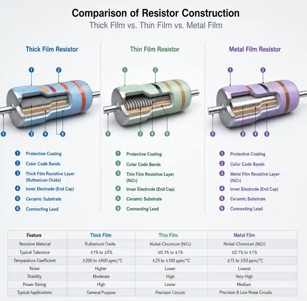 Cross-sectional comparison of thick film, thin film, and metal film resistor construction
Manufacturing technology determines performance across these parameters. Thick film, thin film, and metal film resistors use fundamentally different processes that create distinct material structures, directly controlling tolerance, stability, noise, and reliability.
Selecting a resistor solely by value and package size risks bench success but field failure. A ±5%, ±200 ppm/°C thick film resistor might cost $0.002—ideal for LED current limiting. The same circuit using ±0.1%, ±25 ppm/°C thin film would cost 20× more with no benefit. Conversely, using thick film in a precision voltage reference guarantees drift and calibration problems.
This guide provides practical selection criteria organized by application requirements—helping you match resistor technology to your tolerance budget, thermal environment, frequency needs, and cost constraints.
Thick Film Resistors: Manufacturing and Characteristics
Thick film resistors dominate high-volume production due to low cost, good power handling, and sufficient performance for non-critical applications. The resistive layer is typically 10-20 micrometers thick.
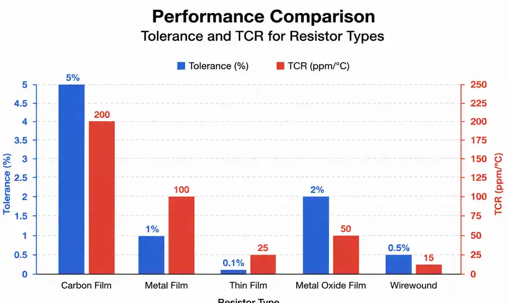 Performance comparison bar chart showing tolerance and TCR for resistor types
Manufacturing process: Screen printing deposits a resistive paste—ruthenium dioxide (RuO₂), glass frit binder, and organic carriers—onto a ceramic substrate (96% alumina). Firing at 850-1000°C burns off organics and fuses particles into a solid layer. Laser trimming adjusts resistance by cutting a spiral pattern.
Paste composition determines resistance range and TCR. Low values (1Ω-10kΩ) have higher metal oxide content and more positive TCR. High values (100kΩ-10MΩ) increase glass content, improving TCR but reducing pulse handling.
Key characteristics:
Tolerance: Standard ±5% to ±1%; ±5% is bulk volume. Tighter tolerances require aggressive trimming and testing. Granular particle structure fundamentally limits tolerance—±0.5% pushes process capability.
TCR: Typically ±200 to ±100 ppm/°C standard; premium reaches ±50 ppm/°C at higher cost. TCR results from differential thermal expansion between particles and glass, creating micro-cracks.
Power handling: Thick film excels—0805 handles 0.125W vs. 0.1W for thin film. The thicker layer and ceramic substrate dissipate heat efficiently. Pulse tolerance is also superior.
Voltage coefficient: Non-uniform layers cause measurable VCR (50-200 ppm/V), significant above 50V or for <100 ppm stability.
Noise: Excess noise exceeds thin/metal film by 10-20 dB due to quantum tunneling between particles—unsuitable for low-noise amplifier inputs or precision audio.
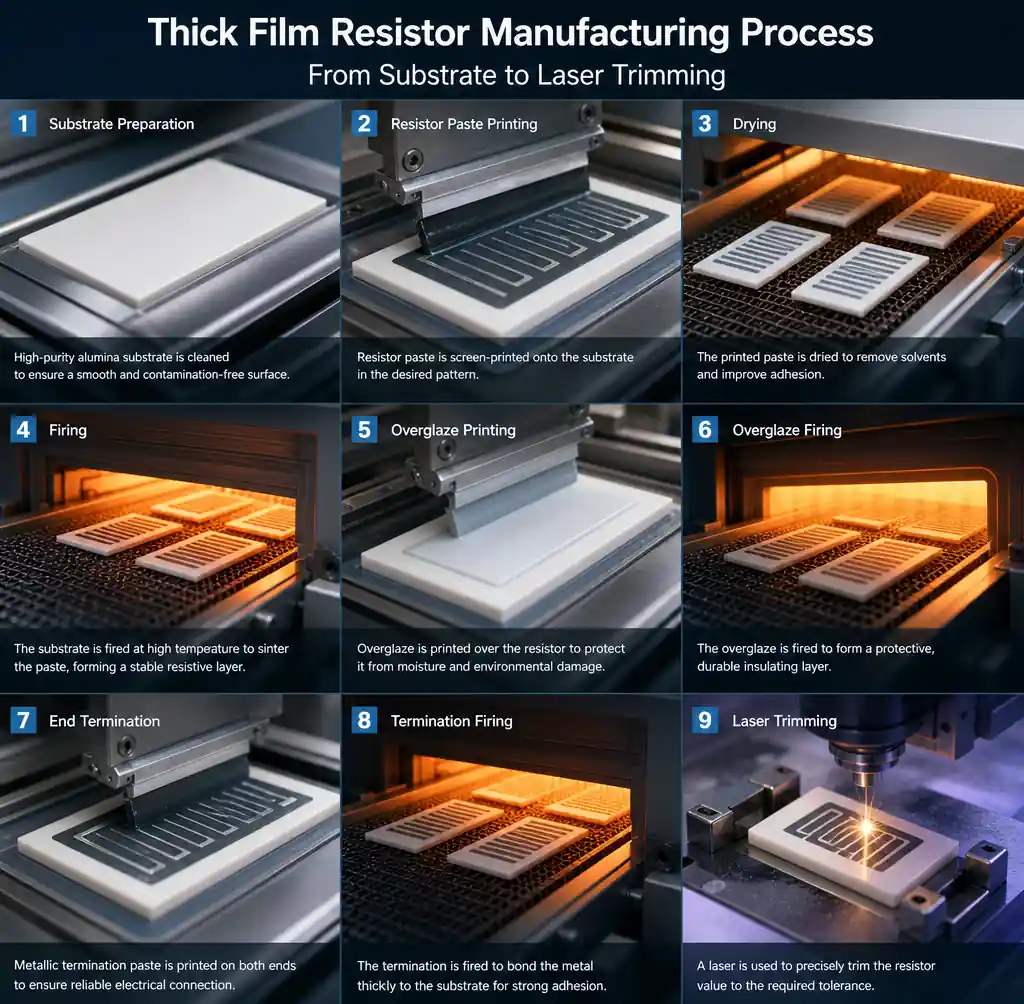 Thick film resistor manufacturing process from substrate to laser trimming
Typical applications: Pull-up/pull-down resistors, LED current limiting, MOSFET gate resistors, non-critical termination, current sensing (where absolute accuracy isn't required), general dividers, power supply filtering, and high-volume consumer products.
Major suppliers: Yageo, Vishay, KOA Speer, Panasonic, Rohm. Extensive ranges from 1Ω to 10MΩ in 0201–2512 packages, with short lead times and deep distributor stock.
Thin Film Resistors: Precision and Performance
Thin film resistors serve applications demanding tight tolerance, excellent TCR, low noise, and stable performance over time and temperature. The resistive layer is 0.01-0.1 micrometers—100× thinner than thick film.
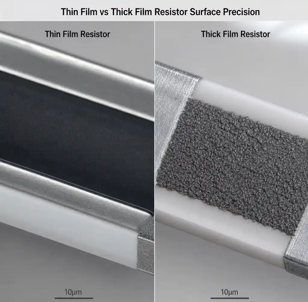 Microscopic comparison of thin film versus thick film resistor surface precision
Manufacturing process: Vacuum deposition (sputtering or evaporation) coats a polished ceramic substrate with a uniform metallic film—nichrome (NiCr), tantalum nitride (TaN), or NiCrSi alloys selected for low TCR and stability. Photolithographic patterning defines resistor geometry with semiconductor-grade precision. Some laser trimming is used, but deposition uniformity often achieves target resistance directly.
Substrate smoothness is critical—surface roughness below 0.1 μm Ra ensures uniformity.
Key characteristics:
Tolerance: Standard ±1% or ±0.5%; ±0.1% and ±0.05% available. Uniform film and precise patterning eliminate local variation. Matched pairs achieve ±0.01% with 10 ppm ratio matching.
TCR: Routinely ±25 to ±50 ppm/°C; premium grades reach ±10 to ±15 ppm/°C. Homogeneous metal film expands uniformly, and alloy tuning can achieve near-zero TCR at room temperature.
Stability and aging: Exceptional long-term stability—typically <100 ppm shift after 1000 hours at rated power. Continuous metal film resists oxidation and mechanical stress better than thick film's particle matrix.
Noise: Minimal excess noise beyond thermal noise—no quantum tunneling. Ideal for low-noise amplifiers, precision ADC inputs, and high-resolution measurements.
Frequency response: Uniform structure creates well-defined parasitics, maintaining accuracy into MHz range. Thick film's granular structure introduces unpredictable high-frequency behavior.
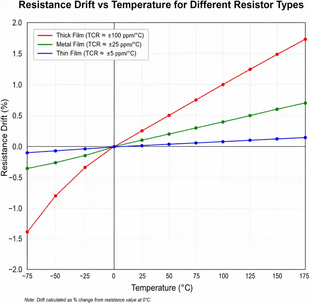 Resistance drift vs temperature graph comparing thick film, metal film, and thin film TCR
Tradeoffs: Lower power handling (0805: 0.1W vs. 0.125W for thick film) and constrained pulse capability. Cost is 5-20× higher than thick film.
Typical applications: Precision voltage dividers for ADC references, instrumentation amplifier gain resistors, matched differential pairs, low-noise amplifier inputs, precision current sensing, calibration standards, high-end audio, RF attenuators, medical instrumentation, and test equipment.
Leading manufacturers: Vishay (Bulk Metal Foil ultra-precision), Susumu, KOA Speer, Viking (Vishay), Bourns. Custom tolerances may require 8-16 week lead times.
Metal Film Resistors: Mainstream Precision
Metal film resistors sit between thick film's cost and thin film's precision. Through-hole versions are common in prototyping, repair, and moderate-volume applications due to favorable price-performance and convenience.
Manufacturing process: A ceramic rod is coated with a thin metal or metal oxide film (nichrome, tin oxide, or tantalum nitride) via vacuum deposition or pyrolysis. A helical groove cuts through the film to adjust resistance.
Cylindrical geometry creates inherent inductance—the spiral forms a coil—limiting high-frequency performance vs. SMD thin film, but this is acceptable for audio and low-frequency precision.
Wire leads attach to metallized end caps, and the assembly is coated for insulation. Color bands indicate resistance value.
Key characteristics:
Tolerance and TCR: Standard ±1% with ±100 to ±50 ppm/°C. Premium offers ±0.5% with ±25 ppm/°C, approaching thin film at moderate cost. Film uniformity exceeds thick film, but cylindrical geometry and wire bonds prevent matching the tightest thin film specs.
Power rating: Through-hole dissipates heat better—¼W and ½W common, 1W+ available. Axial leads provide physical robustness for vibration or handling stress.
Noise: Exceeds thick film but typically falls short of SMD thin film due to helical path and wire-bond interfaces. For audio and moderate precision, noise remains negligible.
Voltage coefficient and stability: Lower VCR than thick film (10-50 ppm/V). Long-term stability rivals thin film when operated well below rated power.
Frequency response: Spiral inductance limits applications below 10 MHz depending on resistance and size. Higher resistance (>100kΩ) has more turns and greater inductance. RF and high-speed digital require SMD options.
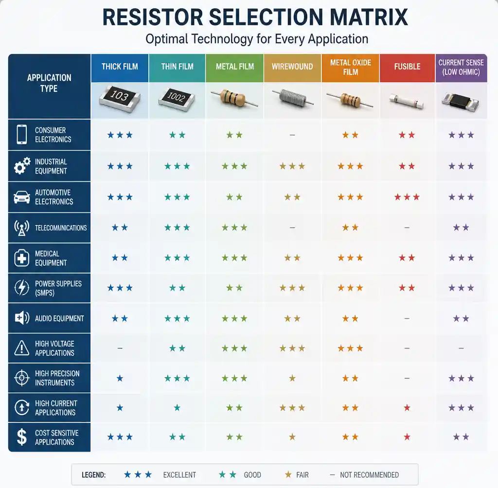 Resistor selection matrix showing optimal technology for each application type
Package options: Predominantly axial through-hole (0204 to large power packages). MELF (cylindrical SMD) combines metal film performance with surface mount convenience, though pick-and-place handles rectangular chips more reliably.
Typical applications: Precision analog circuits in test equipment, audio signal paths, voltage references, prototyping, repair, hobbyist projects, precision current sensing, legacy industrial equipment, and educational electronics.
Major suppliers: Vishay, KOA Speer, Yageo (Teapo), Panasonic, Bourns. Excellent availability through distribution.
Performance Comparison: Tolerance, TCR, and Power Rating
| Parameter | Thick Film (SMD) | Metal Film (TH) | Thin Film (SMD) |
|---|---|---|---|
| Tolerance | ±5% to ±1% standard ±0.5% premium |
±1% standard ±0.5% to ±0.1% premium |
±1% to ±0.1% standard ±0.05% to ±0.01% available |
| TCR (ppm/°C) | ±200 to ±100 standard ±50 premium |
±100 to ±50 standard ±25 premium |
±50 to ±25 standard ±10 to ±5 premium |
| Power (0805) | 0.125W typical 0.25W high-power |
0.25W (¼W TH) 0.5W (½W TH) |
0.1W typical 0.125W high-power |
| Voltage Coefficient | 50-200 ppm/V | 10-50 ppm/V | <10 ppm/V |
| Noise (excess) | -20 to -30 dB | -30 to -40 dB | -40 to -50 dB |
| Long-term Stability | ±500 ppm typical | ±200 ppm typical | <±100 ppm typical |
| Frequency Response | DC to 100 MHz (low R) | DC to 10 MHz (spiral inductance) | DC to 500 MHz+ |
| Relative Cost (0805, 1%) | 1× baseline | 2-3× (through-hole) | 5-10× |
Tolerance selection: Digital circuits and non-critical analog use ±5% thick film. ADC dividers or op-amp feedback need ±1% or better. Precision instrumentation requiring <0.1% accuracy demands thin film.
TCR impact: Calculate worst-case shift: ΔR = R × TCR × ΔT. A 10kΩ resistor with ±100 ppm/°C TCR from 0°C to 70°C shifts 70 × 70 = 4900 ppm = ±4.9%—adding to tolerance. Select TCR grades that maintain accuracy across the full operating range.
Power derating: All types derate linearly from full power at 70°C to zero at maximum operating temperature (typically 155-175°C). A 0.125W resistor at 85°C may only safely dissipate 0.09W continuous. Check manufacturer curves.
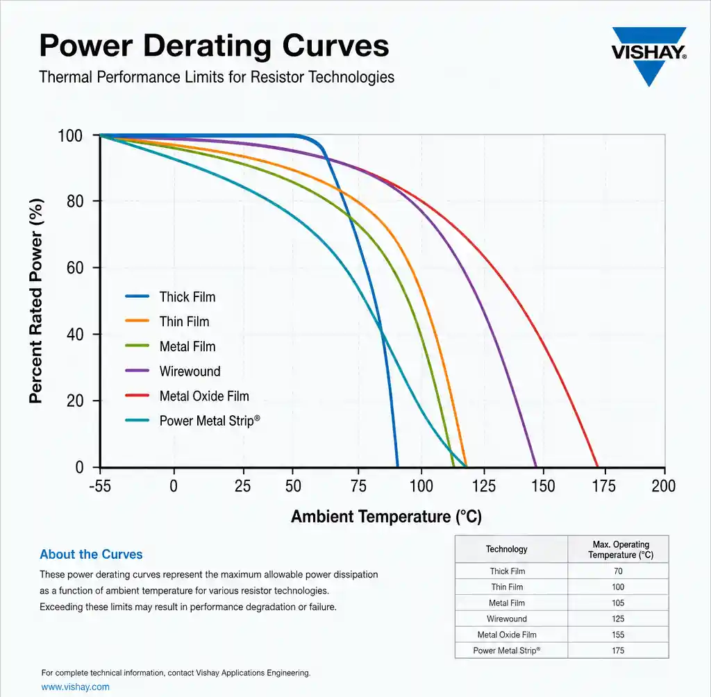 Power derating curves showing thermal performance limits for resistor technologies
Voltage Coefficient and Pulse Handling
Voltage coefficient of resistance (VCR): Thick film shows 50-200 ppm/V due to quantum tunneling. At 100V, resistance shifts 1%. Thin film's homogeneous structure minimizes VCR below 10 ppm/V. Metal film falls between at 10-50 ppm/V. For high-voltage precision, specify low-VCR resistors or compensate in firmware.
Pulse and surge handling: Thick film tolerates transient overload better—greater thermal mass in the resistive layer absorbs 10× power pulses for 1-10 ms. Thin film, with 100× less thermal mass, fails rapidly under overload. Verify pulse energy specs (joules) rather than assuming continuous power rating translates.
ESD sensitivity: All types resist ESD well vs. semiconductors, but high-resistance values (>1MΩ) can suffer from kV ESD strikes—thin film is most vulnerable. Add parallel ESD protection for exposed high-impedance circuits.
Cost Analysis and Procurement Considerations
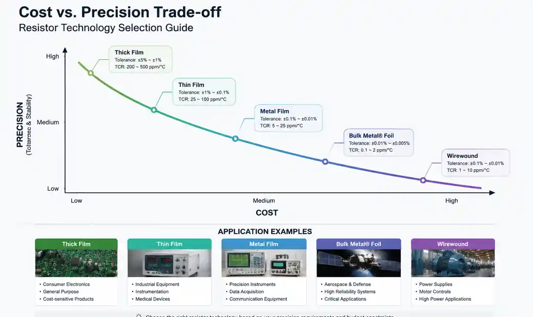 Cost vs precision trade-off chart with resistor technology application examples
Unit pricing (1000-piece volumes, 2026):
- Thick film 0805, 10kΩ ±5%: $0.002-0.005
- Thick film 0805, 10kΩ ±1%: $0.004-0.008
- Metal film ¼W, 10kΩ ±1%: $0.01-0.02
- Thin film 0805, 10kΩ ±0.1%: $0.05-0.15
- Thin film 0805, 10kΩ ±0.01%: $0.20-0.50
Volume pricing improves at 10k+ quantities; thick film approaches $0.001/piece in reels of 10,000. Thin film shows less aggressive discounting—0.1% parts rarely drop below $0.03 even at 100k.
Standardization benefits: Limiting designs to curated resistor values and types reduces procurement complexity and improves pricing leverage. Many companies standardize on E24 series values in two grades—±5% thick film for non-critical, ±1% thin film for precision.
Supply chain: Thick film and metal film are interchangeable across multiple vendors, enabling second-sourcing. Thin film, especially tight tolerances, often requires vendor-specific qualification. Qualify at least two thin film suppliers for production designs.
Lead times: Commodity resistors ship next-day. Custom tolerance thin film or non-standard values may require 12-20 weeks. Consider stocking strategic thin film values for critical designs.
Application Guidelines: Which Resistor for Which Circuit
Power supply and distribution: Use thick film for current sensing, load resistors, bleeding resistors, and feedback dividers where ±3-5% suffices. Switch to thin film only when feedback accuracy directly impacts regulation (e.g., ±0.1% voltage sources).
Digital circuits: Pull-up, pull-down, and termination almost always use thick film ±5%. Logic thresholds dwarf resistor tolerance effects. Save cost throughout digital sections unless controlled-impedance or precision timing requires tighter tolerance.
Precision analog and measurement: ADC references, instrumentation amplifier gain resistors, precision current sources, and calibration circuits demand thin film. For 16-bit (0.0015%) accuracy, use ±0.01% thin film with TCR ≤±10 ppm/°C and verify ratio matching.
Audio signal paths: Metal film through-hole serves prototyping and boutique audio. Production equipment uses thin film SMD for cost and density. Thick film's excess noise makes it unsuitable for low-level audio inputs (<1 mV).
RF and high-frequency: SMD thin film minimizes parasitic inductance critical above 100 MHz. Thick film works below 100 MHz in small packages (0402, 0603). Avoid metal film for RF due to spiral inductance. For 50Ω terminations and antenna matching, specify thin film.
High voltage (>100V): Low VCR is essential. Thin film maintains <0.1% voltage coefficient; thick film may shift 1% or more. Metal film offers a cost-effective middle ground for moderate-accuracy high-voltage applications.
FAQ
Can I substitute thick film for thin film to save cost?
Only if you recalculate your error budget including degraded tolerance and TCR. If your circuit maintains acceptable performance with ±1% and ±100 ppm/°C, substitution works. If not, the cost saving disappears with yield loss or returns.
Why do some metal film resistors cost more than equivalent thin film SMD?
Through-hole manufacturing adds wire bonding, lead forming, and coating steps. Low-volume tight-tolerance metal film also incurs testing costs. For production, thin film SMD almost always delivers better cost with automated assembly.
How do I select resistor tolerance for voltage dividers?
Use worst-case analysis: V_out = V_in × [R2/(R1+R2)]. For a 2:1 divider with ±1% resistors, worst case yields approximately ±2% output error. If your circuit tolerates that, ±1% suffices. Otherwise, specify tighter tolerance or use a ratio-matched network (ratio tolerance typically ±0.05%).
Do I need to derate power for SMD resistors?
Yes, particularly with limited PCB copper for heat sinking. An 0805 on FR4 with minimal copper may only safely dissipate 60-70% of rated power. Increase copper area, choose larger packages, or parallel resistors. Thermal simulation or prototyping prevents failures.
Can automotive or industrial circuits use thick film resistors?
Yes, but specify AEC-Q200 qualified thick film for wider temperature ranges and higher reliability. These grades typically offer ±100 ppm/°C TCR vs. standard ±200 ppm/°C and undergo additional testing. The premium is modest (10-30%) and improves field reliability.
Conclusion
Resistor technology selection directly impacts circuit performance, manufacturing cost, and long-term reliability. Thick film serves cost-sensitive applications where ±1-5% tolerance and ±100-200 ppm/°C TCR suffice—covering the vast majority of circuits. Metal film through-hole balances moderate precision with convenience for prototyping, repair, and low-volume production. Thin film addresses precision instrumentation and analog applications where tolerance below ±0.1%, TCR under ±25 ppm/°C, and low noise justify 5-20× cost premiums.
For procurement managers and design engineers, the key is matching technology to actual circuit requirements rather than over-specifying. Over-specification wastes cost; under-specification triggers redesigns or failures. Calculate your error budget, factor in temperature effects, and select the most cost-effective resistor that reliably meets total accuracy requirements across production tolerances and environmental conditions.
As manufacturing scales, thick film performance improves while thin film costs decline—narrowing the gap. Understanding these trade-offs enables informed sourcing decisions that optimize both circuit performance and component cost.
