


Bridge Rectifier: Complete Guide to AC-DC Conversion Circuits
Converting AC to DC power is fundamental in modern electronics. Bridge rectifiers make this conversion efficient and reliable, powering everything from your smartphone charger to industrial equipment. This guide explains how bridge rectifiers work, their applications, and how to choose the right one for your project.
Table of Contents
- What is a Bridge Rectifier?
- How Does a Bridge Rectifier Work?
- Bridge Rectifier Circuit Configuration
- Key Specifications and Parameters
- Types of Bridge Rectifiers
- Bridge Rectifier vs Other Rectifier Designs
- Common Applications
- Troubleshooting Common Problems
- How to Select the Right Bridge Rectifier
1. What is a Bridge Rectifier?
A bridge rectifier is an electronic circuit that converts alternating current (AC) into direct current (DC) using four diodes arranged in a specific bridge configuration. It's called a "bridge" because the four diodes form a diamond or square pattern that resembles a bridge structure.
Unlike simpler rectifier designs, bridge rectifiers utilize both the positive and negative halves of the AC waveform, making them significantly more efficient. This full-wave rectification produces smoother DC output with less ripple, which is essential for powering sensitive electronic devices.
The bridge rectifier is considered the industry standard for AC-DC conversion because it doesn't require a center-tapped transformer, making it more practical and cost-effective for most applications.
2. How Does a Bridge Rectifier Work?
The bridge rectifier operates through a clever arrangement of four diodes that work in pairs. During each half-cycle of the AC input, two diodes conduct while the other two remain off.
Positive Half-Cycle: When the AC input is positive, diodes D1 and D3 conduct (forward-biased), allowing current to flow through the load resistor. Diodes D2 and D4 remain reverse-biased and block current flow.
Negative Half-Cycle: When the AC input swings negative, diodes D2 and D4 conduct, redirecting the current through the load in the same direction as before. Meanwhile, D1 and D3 are reverse-biased and don't conduct.
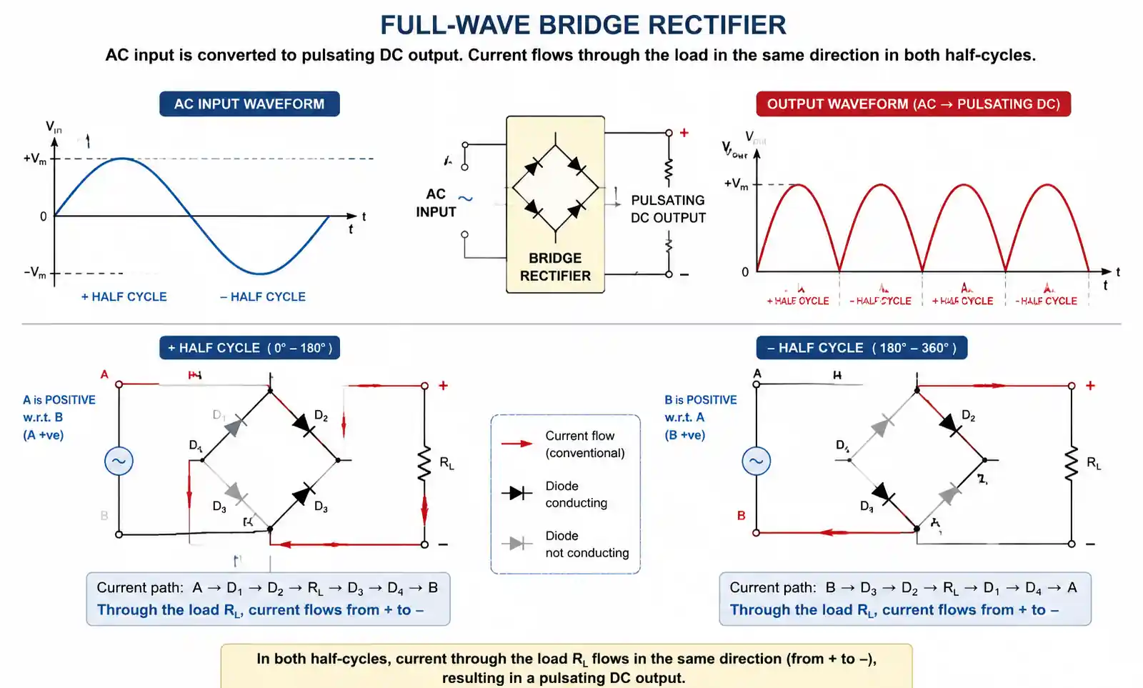
The result is that current always flows in the same direction through the load, regardless of the AC polarity. This converts the bidirectional AC waveform into unidirectional pulsating DC output at twice the input frequency.
For example, with 60 Hz AC input, the output ripple frequency becomes 120 Hz, making it easier to filter into smooth DC voltage.
3. Bridge Rectifier Circuit Configuration
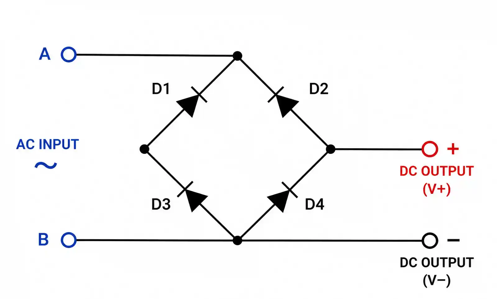
The bridge rectifier consists of four diodes connected to form a closed loop with the AC input on one axis and the DC output on the other axis.
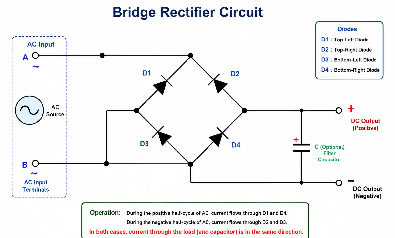
Circuit Components:
- Four Diodes (D1-D4): Arranged in a bridge pattern with alternating polarity
- AC Input: Connected to the two opposite corners of the bridge
- DC Output: Taken from the remaining two corners
- Optional Filter Capacitor: Connected across the output to smooth ripple
The beauty of this configuration is its simplicity—no center-tapped transformer required. You can connect it directly to any AC source, and it automatically handles both half-cycles to produce DC output.
Polarity Marking: Most packaged bridge rectifiers have clear markings: AC input terminals are marked with "~" or "AC," while DC output terminals are marked "+" and "-" to prevent incorrect connections.
4. Key Specifications and Parameters
Understanding bridge rectifier specifications helps you choose the right component for your application.
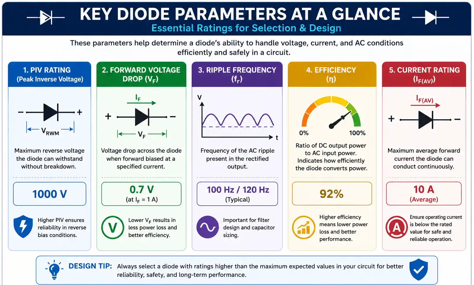
Peak Inverse Voltage (PIV): Each diode must withstand the maximum AC input voltage when reverse-biased. For a bridge rectifier, PIV equals the peak AC voltage (Vm). Always select diodes with PIV ratings at least 20-30% higher than your expected peak voltage for safety margin.
Forward Voltage Drop: Standard silicon diodes drop approximately 0.7V when conducting. Since two diodes conduct simultaneously in a bridge configuration, the total voltage drop is about 1.4V. Schottky diodes reduce this to around 0.6V total (0.3V per diode), improving efficiency in low-voltage applications.
Ripple Frequency: Bridge rectifiers produce ripple at twice the AC input frequency:
- 50 Hz AC input → 100 Hz ripple
- 60 Hz AC input → 120 Hz ripple
Higher ripple frequency is easier to filter, requiring smaller capacitors.
Efficiency: Theoretical maximum efficiency is 81.2%, but practical efficiency is typically 75-80% due to diode voltage drops and other losses.
Current Rating: Select a bridge rectifier with current rating 1.5-2× your expected load current to handle surge conditions and maintain reliability.
5. Types of Bridge Rectifiers
Bridge rectifiers come in various configurations to suit different applications.
Single-Phase Bridge Rectifiers: The most common type, used in household electronics and small power supplies. Available as discrete diodes or integrated modules with current ratings from 1A to over 50A.
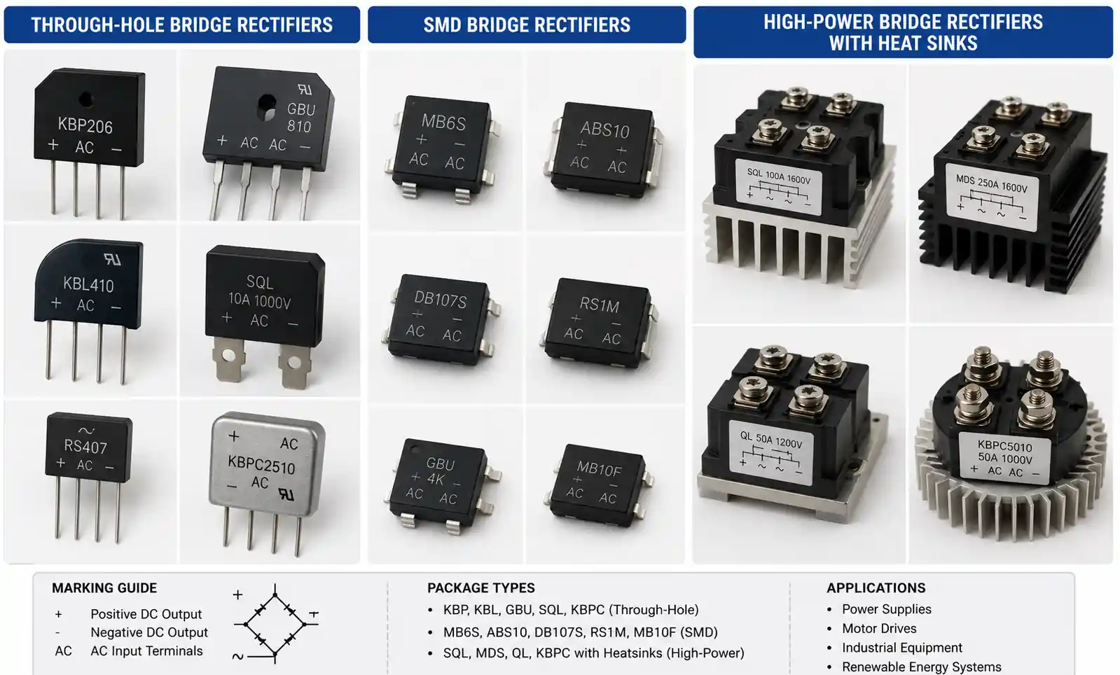
Three-Phase Bridge Rectifiers: Used in industrial applications and high-power systems, three-phase bridge rectifiers use six diodes to convert three-phase AC into DC. They provide smoother output with less ripple than single-phase designs.
Integrated Bridge Modules: Pre-packaged units with all four diodes in a single case, available in various form factors:
- Through-hole packages (square or rectangular)
- Surface-mount (SMD) packages like MB6S
- High-power modules with heat sinks
Controlled Bridge Rectifiers: Use thyristors (SCRs) instead of diodes, allowing voltage control by adjusting the firing angle. Common in variable-speed motor drives and industrial power supplies.
Recent Innovation - Superconducting Bridge Rectifiers (2025): Research published in 2025 demonstrated superconducting bridge rectifiers achieving 42-43% rectification efficiency at frequencies up to 40 kHz, opening possibilities for quantum circuit applications.
6. Bridge Rectifier vs Other Rectifier Designs
Understanding the differences helps you choose the right rectifier topology.
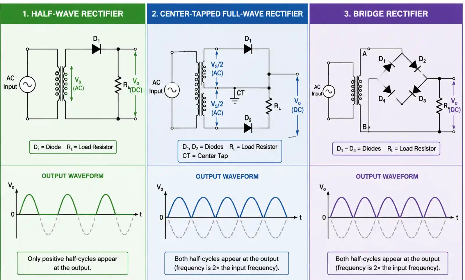
Bridge Rectifier vs Half-Wave Rectifier:
Half-wave rectifiers use only one diode and rectify only half the AC waveform. While simpler and cheaper, they waste 50% of the input power and produce significant ripple. Bridge rectifiers are far superior for most applications.
Bridge Rectifier vs Center-Tapped Full-Wave Rectifier:
The center-tapped design uses only two diodes but requires a center-tapped transformer. Here's the comparison:
| Feature | Bridge Rectifier | Center-Tapped |
|---|---|---|
| Diodes Required | 4 | 2 |
| Transformer | Standard | Center-tapped |
| Voltage Drop | 1.4V (2 diodes) | 0.7V (1 diode) |
| Transformer Utilization | Better | Lower |
| Cost | Lower (no special transformer) | Higher |
| Output Voltage | Higher | Lower |
For example, a 24V transformer with a bridge rectifier outputs about 34V peak DC, while a 12+12V center-tapped transformer with two-diode rectification outputs only about 17V peak DC.
Why Bridge Rectifiers Are Preferred:
- No center-tapped transformer needed (cheaper, more available)
- Better transformer utilization
- More practical for most designs
- Slight disadvantage in voltage drop is outweighed by other benefits
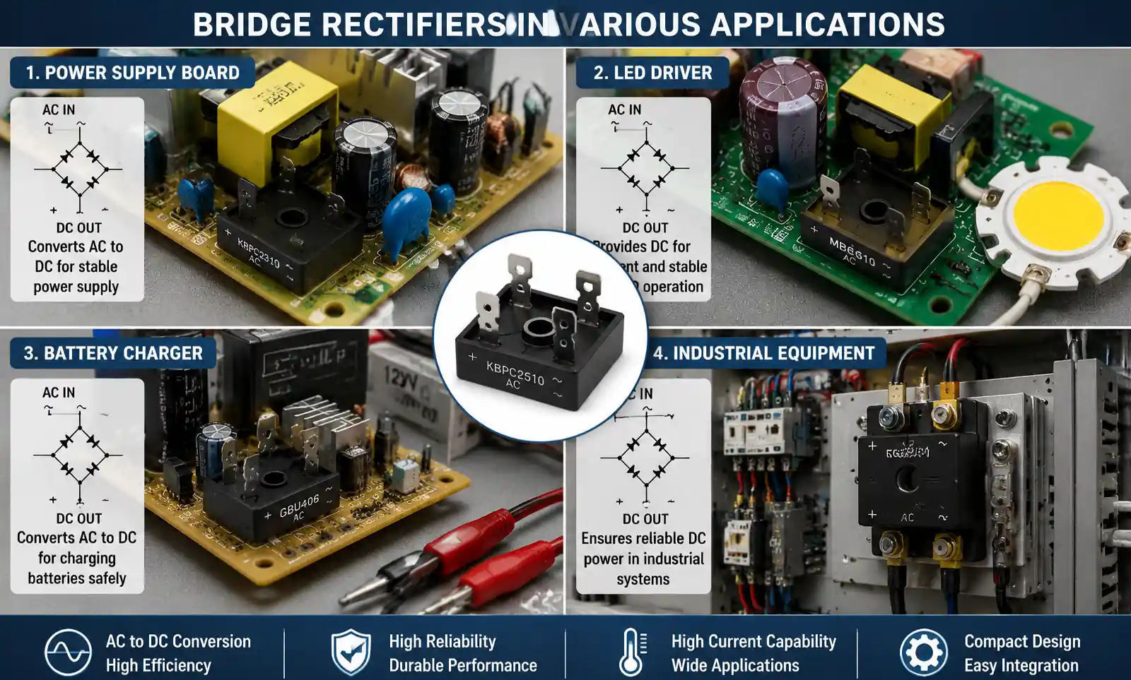
7. Common Applications
Bridge rectifiers are ubiquitous in power electronics across numerous industries.
Consumer Electronics:
- Smartphone and laptop chargers
- LED lighting power supplies
- Home appliances
- Audio equipment power supplies
Industrial Applications:
- Variable frequency drives (VFDs)
- Battery charging systems
- Electric welding equipment
- Industrial automation and control systems
Automotive:
- Alternator rectification systems
- Battery management
- Electric vehicle charging stations
Telecommunications:
- Radio transmitters and receivers
- Communication equipment power supplies
- Base station power systems
Renewable Energy:
- Solar inverter input stages
- Wind turbine rectification
- Energy storage system interfaces
The bridge rectifier's reliability, efficiency, and simplicity make it the go-to choice whenever AC power needs conversion to DC.
8. Troubleshooting Common Problems
Recognizing and fixing bridge rectifier issues quickly prevents system failures.

Problem 1: Half-Wave Output Instead of Full-Wave
Symptoms: Output voltage drops to approximately half the expected value.
Cause: One or more diodes failed open circuit.
Solution: Test each diode individually with a multimeter in diode test mode. Replace the entire bridge module or the failed discrete diode(s).
Problem 2: No Output or Very Low Output
Symptoms: Little or no DC voltage at the output terminals.
Causes:
- Bridge rectifier installed backward (incorrect polarity)
- All diodes failed
- Poor connections or broken traces
Solution: Verify correct orientation by checking polarity markings. Test diodes individually. Check PCB traces for damage, especially after overvoltage events.
Problem 3: Lower Than Expected Output Voltage
Symptoms: Output voltage is present but lower than calculations predict.
Causes:
- Insufficient load (no load resistor in testing)
- Higher than expected voltage drop
- Weak AC input
Solution: Connect appropriate load resistor across output terminals during testing. Verify AC input voltage with a multimeter. Account for 1.4V diode drop in calculations.
Problem 4: Overheating and Thermal Shutdown
Symptoms: Bridge rectifier becomes very hot, intermittent output.
Causes:
- Current rating too low for application
- Poor heat sinking
- Excessive load current
Solution: Upgrade to higher current rating bridge rectifier. Add proper heat sink. Verify load current is within specifications.
Problem 5: Blown Bridge Rectifier
Symptoms: Complete failure, often with visible damage.
Causes:
- Overvoltage spike
- Reverse polarity connection
- Current surge exceeded ratings
Solution: Add surge protection (MOVs or TVS diodes). Verify correct polarity before powering. Use higher PIV rating and current capacity.
Testing Procedure:
- Disconnect power and discharge capacitors
- Remove bridge rectifier from circuit
- Test each diode with multimeter in diode mode
- Check for short circuits between AC and DC terminals
- Verify proper orientation before reinstallation
9. How to Select the Right Bridge Rectifier
Choosing the appropriate bridge rectifier ensures reliable operation and long service life.
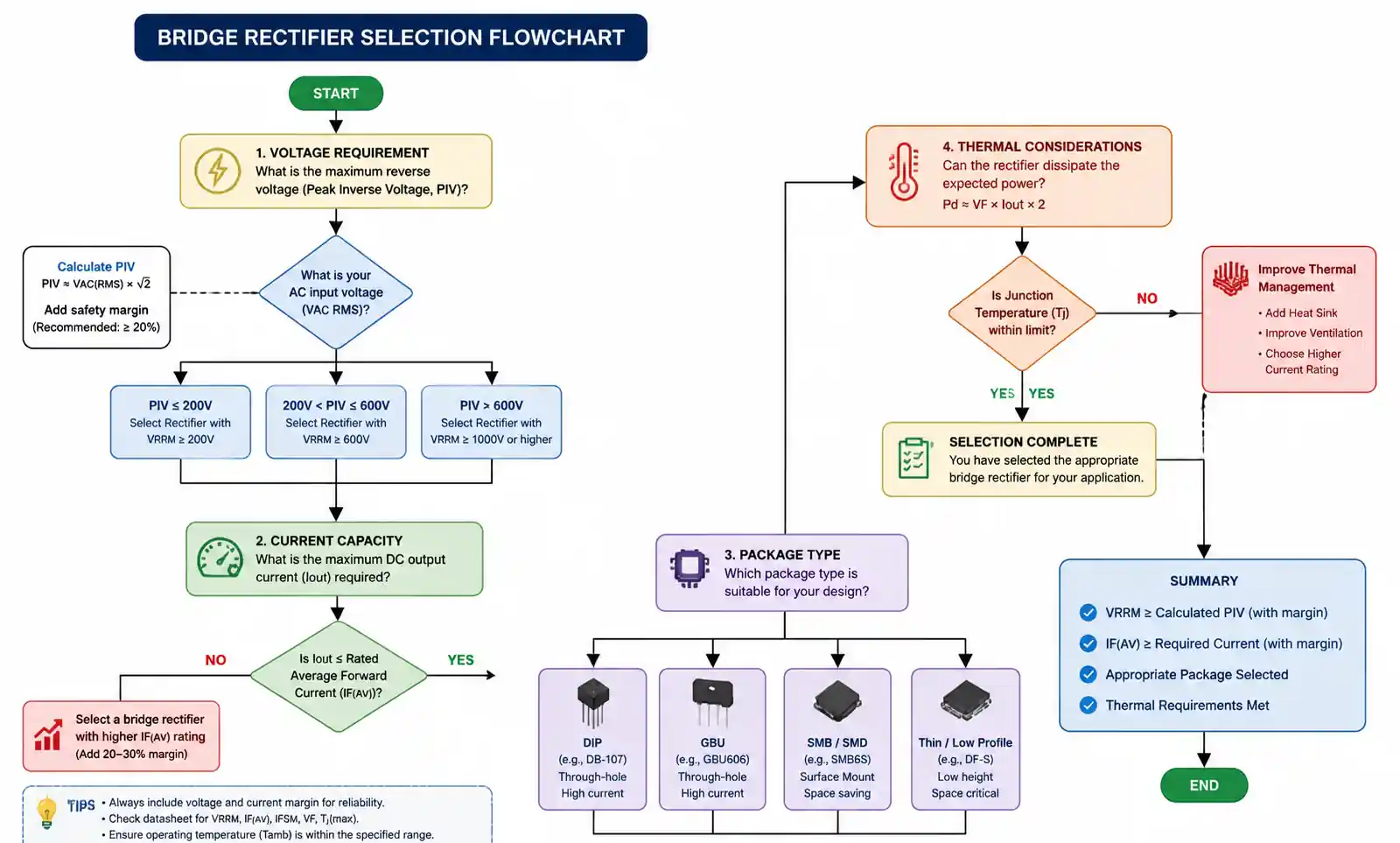
Step 1: Determine Voltage Requirements
Calculate the peak AC input voltage (Vm = Vrms × √2). Select a bridge rectifier with PIV rating at least 1.3× the peak voltage for safety margin.
Example: For 120V AC, peak voltage = 120 × 1.414 = 170V. Choose bridge rectifier rated for at least 220V PIV.
Step 2: Calculate Current Requirements
Determine maximum load current including surge conditions. Select bridge rectifier rated for 1.5-2× the expected average current.
Example: For 2A average load, choose a bridge rectifier rated for 3-4A minimum.
Step 3: Consider Voltage Drop
Standard silicon diodes: 1.4V total drop Schottky diodes: 0.6V total drop
For low-voltage applications (5V, 12V), Schottky bridge rectifiers improve efficiency significantly.
Step 4: Evaluate Thermal Requirements
Calculate power dissipation: P = 1.4V × Iload
Ensure adequate heat sinking if power dissipation exceeds 1-2W. High-power applications may require bridge rectifiers with integrated heat sinks or external heat sink mounting.
Step 5: Choose Package Type
- Through-hole: Easy prototyping, robust connections
- Surface-mount: Compact, automated assembly
- Modular: High current, industrial applications
Step 6: Consider Special Requirements
- Fast recovery diodes for high-frequency switching applications
- Automotive-grade for harsh environments
- Low-leakage types for precision applications
Quick Selection Guide:
| Application | Voltage | Current | Recommended Type |
|---|---|---|---|
| Phone charger | 400V PIV | 1-2A | Standard SMD bridge |
| LED driver | 600V PIV | 500mA-1A | Compact through-hole |
| Battery charger | 200V PIV | 5-10A | Module with heat sink |
| Industrial power supply | 600V+ PIV | 25-50A | Three-phase module |
| Low-voltage (5V/12V) | 100V PIV | 3-5A | Schottky bridge |
Quality Considerations:
Reputable manufacturers (Vishay, ON Semiconductor, Diodes Incorporated, IXYS) provide consistent quality and detailed datasheets. Avoid generic unmarked components for critical applications.
Conclusion
Bridge rectifiers are essential building blocks in power electronics, efficiently converting AC to DC through their elegant four-diode configuration. Their widespread adoption stems from practical advantages: no center-tapped transformer required, excellent transformer utilization, and reliable full-wave rectification.
Whether you're building a simple power supply or designing industrial equipment, understanding bridge rectifier operation, specifications, and selection criteria ensures optimal performance. The recent advances in superconducting rectifier technology hint at exciting future developments, though traditional silicon bridge rectifiers will remain the workhorse of AC-DC conversion for years to come.
By following proper selection guidelines, implementing adequate filtering, and applying correct troubleshooting techniques, you can leverage bridge rectifiers effectively in virtually any AC-DC conversion application.