


Bridge Rectifier Selection Guide: Circuit Design, Parameters, and Applications
Converting AC to DC power is a fundamental requirement in modern electronics. Whether you're designing a power supply for industrial equipment, automotive systems, or consumer devices, selecting the right bridge rectifier directly impacts efficiency, reliability, and total system cost. This guide walks through the technical parameters, selection methodology, and design considerations that matter most to engineers and procurement teams.
Table of Contents
- What is a Bridge Rectifier and How Does It Work
- Key Technical Parameters Explained
- How to Choose the Right Bridge Rectifier for Your Application
- Performance Comparison: Discrete vs. Integrated Bridge Rectifiers
- Design Considerations and Common Pitfalls
- Supply Chain and Sourcing Considerations
- FAQ
- Conclusion and Recommended Next Steps
1. What is a Bridge Rectifier and How Does It Work
A bridge rectifier is a full-wave rectifier circuit that converts alternating current (AC) to pulsating direct current (DC) using four diodes arranged in a bridge configuration. Unlike half-wave rectifiers that waste half of the AC cycle, bridge rectifiers utilize both positive and negative half-cycles, delivering twice the output frequency and significantly better DC output characteristics.
The circuit operates by conducting two diodes during each half-cycle: during the positive half-cycle, diodes D1 and D2 conduct, directing current through the load in one direction; during the negative half-cycle, diodes D3 and D4 conduct, maintaining the same current direction through the load. This configuration eliminates the need for a center-tapped transformer, reducing transformer cost and complexity in most power supply designs.
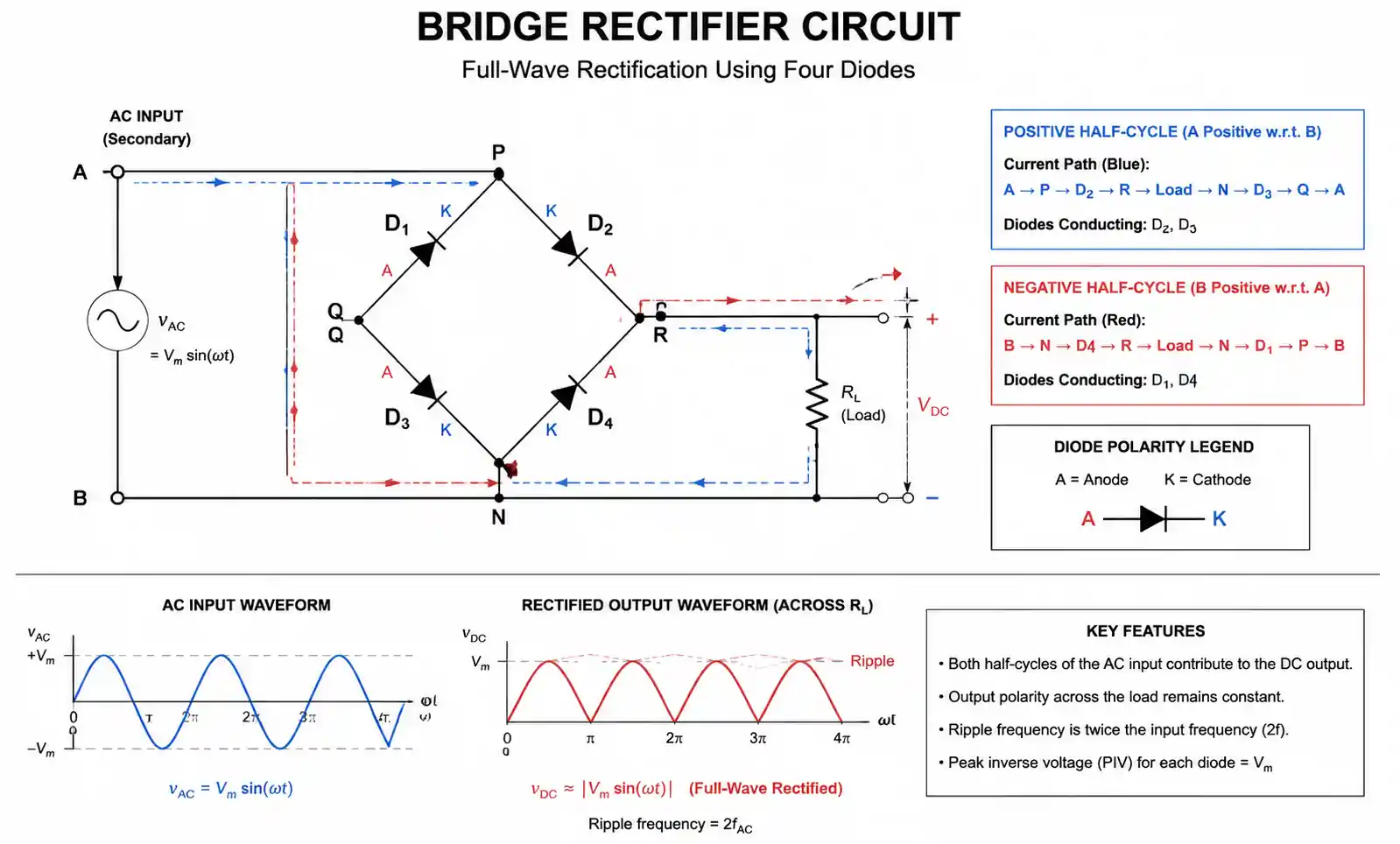
Bridge rectifiers are available in two primary forms: discrete component designs using individual diodes, and integrated bridge rectifier modules that package all four diodes in a single component with standardized pinouts. The choice between these implementations depends on power level, thermal management requirements, PCB space constraints, and cost targets.
2. Key Technical Parameters Explained
Selecting the appropriate bridge rectifier requires understanding several critical parameters that directly affect circuit performance and reliability.
Peak Reverse Voltage (PRV or VRRM): This specification defines the maximum voltage each diode must withstand when reverse-biased. In a bridge rectifier, each diode experiences the full peak AC input voltage plus the DC output voltage during its non-conducting period. For safety margin, select a VRRM rating at least 1.5 to 2 times your peak AC input voltage. For a 230VAC input (325V peak), specify diodes with minimum 600V VRRM, though 800V or 1000V parts provide better reliability margin.
Forward Current Rating (IF(AV)): This parameter specifies the average forward current the rectifier can continuously handle under defined thermal conditions. Pay close attention to the thermal environment specification—most datasheets rate current at a specific case temperature (typically 50°C, 75°C, or 100°C). At higher ambient temperatures or with inadequate heatsinking, actual current capacity decreases significantly. A 25A-rated bridge rectifier at 50°C case temperature may only handle 15A at 100°C.
Forward Voltage Drop (VF): Each conducting diode in the bridge drops voltage, and since two diodes conduct simultaneously, total power loss equals 2 × VF × IL. Standard silicon diodes typically drop 0.7-1.0V per junction. Schottky diodes reduce this to 0.3-0.5V, significantly improving efficiency in low-voltage, high-current applications. For a 5V/10A output, reducing VF from 0.9V to 0.4V per diode decreases power loss from 18W to 8W—a substantial improvement.
| Parameter | Standard Silicon | Fast Recovery | Schottky | Ultra-Fast |
|---|---|---|---|---|
| Forward Voltage Drop (VF) | 0.8-1.0V | 0.8-1.1V | 0.3-0.5V | 0.9-1.2V |
| Reverse Recovery Time (trr) | 2-5μs | 35-75ns | <10ns | 25-35ns |
| Typical Applications | 50/60Hz mains | SMPS up to 100kHz | Low voltage DC/DC | High frequency SMPS |
| Cost Relative to Standard | Baseline | 1.3-1.8× | 1.5-2.5× | 2.0-3.0× |
| Max Junction Temp | 150-175°C | 150-175°C | 125-150°C | 150-175°C |
This comparison table highlights the fundamental trade-off between switching speed and forward voltage drop. Schottky rectifiers excel in low-voltage applications where conduction loss dominates, while fast recovery and ultra-fast diodes are essential for high-frequency switching applications despite their higher VF.
Reverse Recovery Time (trr): In switching power supplies, diode reverse recovery causes current spikes, EMI, and switching losses. Standard rectifier diodes with trr of 2-5μs are suitable only for line-frequency (50/60Hz) applications. Switch-mode power supplies operating at 50-150kHz require fast recovery diodes (trr < 75ns) or ultra-fast diodes (trr < 35ns). Schottky diodes have minimal reverse recovery due to their majority-carrier operation, making them ideal for high-frequency rectification up to several hundred kHz.
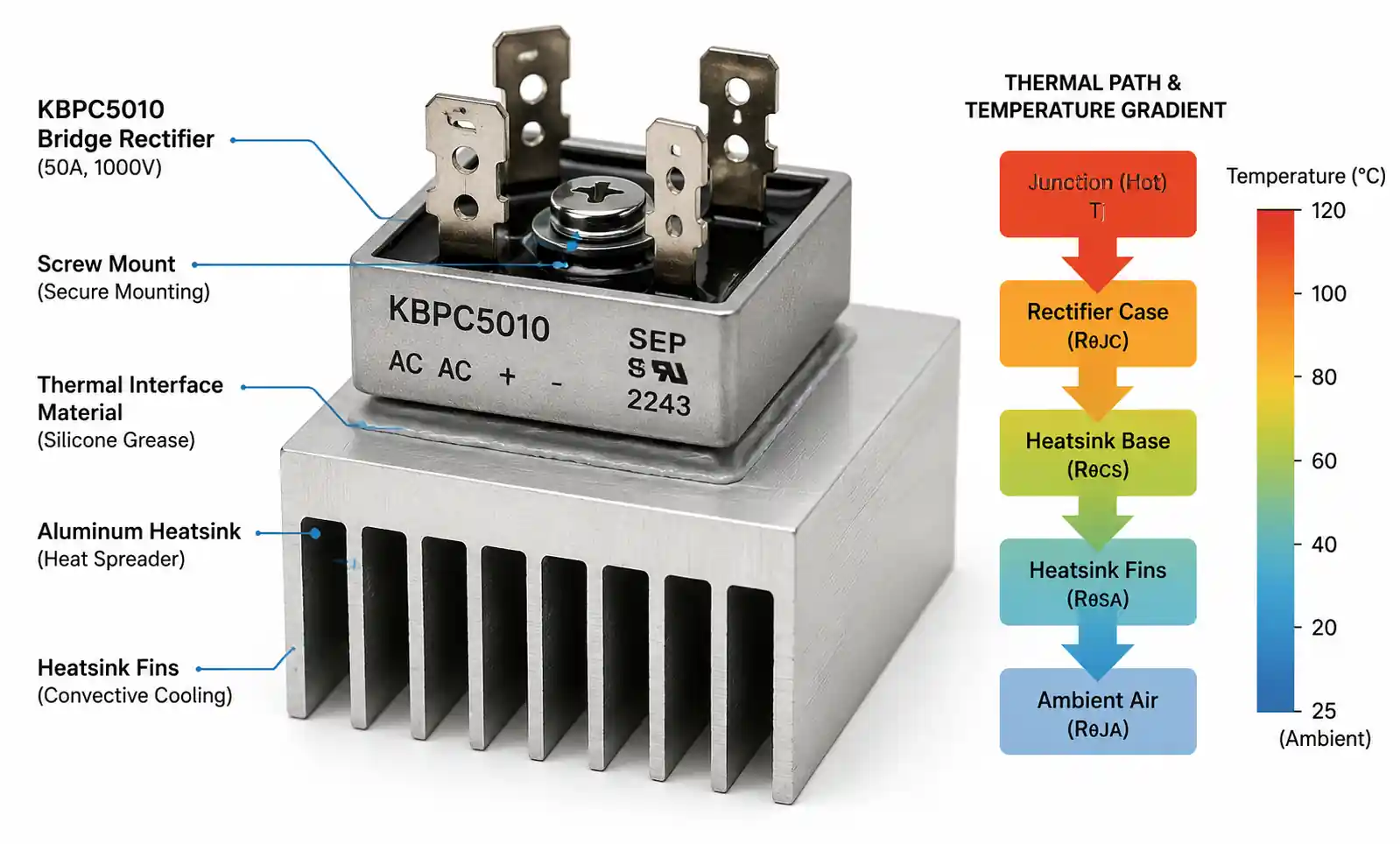
Thermal Resistance (RθJC and RθJA): These parameters determine how effectively heat transfers from the junction to the case (RθJC) and from the junction to ambient air (RθJA). Lower thermal resistance values indicate better heat dissipation capability. For reliable operation, ensure junction temperature remains below the maximum rating (typically 150-175°C) under worst-case conditions. Calculate using: TJ = TA + (Power Loss × RθJA), or with heatsink: TJ = TA + (Power Loss × (RθJC + RθCS + RθSA)).
3. How to Choose the Right Bridge Rectifier for Your Application
Bridge rectifier selection follows a systematic methodology that accounts for electrical requirements, thermal constraints, and application-specific conditions.
Step 1: Define Input and Output Requirements. Start by documenting AC input voltage range (including tolerance and transient conditions), required DC output voltage and current, expected load regulation requirements, and operating frequency. For universal input power supplies (85-265VAC), this determines the VRRM requirement. For 24VAC industrial control supplies, lower voltage ratings suffice but thermal design becomes more critical due to higher currents.
Step 2: Calculate Current Rating with Safety Margin. The average current through each diode equals half the DC load current, but RMS current determines heating. For capacitor-input filters (most common topology), high peak charging currents flow through the rectifier during the brief conduction period. Use the form factor from your specific application—typical capacitor-input filters require rectifiers rated for 1.5-1.8× the DC output current. A 10A DC output typically requires a bridge rectifier rated for 15-18A average forward current.
Step 3: Evaluate Power Loss and Thermal Design. Calculate total power dissipation: P = 2 × VF × IDC(avg). Verify that junction temperature remains within limits: TJ(max) = TA(max) + (P × RθJA). If TJ exceeds 125°C, consider using Schottky diodes for lower VF, adding a heatsink to reduce thermal resistance, selecting a larger package with better RθJC, or paralleling multiple rectifiers to distribute heat.
Step 4: Select Diode Type Based on Operating Frequency. Line-frequency applications (50/60Hz transformers) work well with standard silicon rectifiers—lowest cost, highest current ratings. Switching frequencies 20-100kHz require fast recovery diodes to minimize switching losses and EMI. High-frequency applications above 100kHz benefit from ultra-fast or Schottky diodes. Low-voltage outputs (<24VDC) almost always justify Schottky rectifiers due to conduction loss savings.
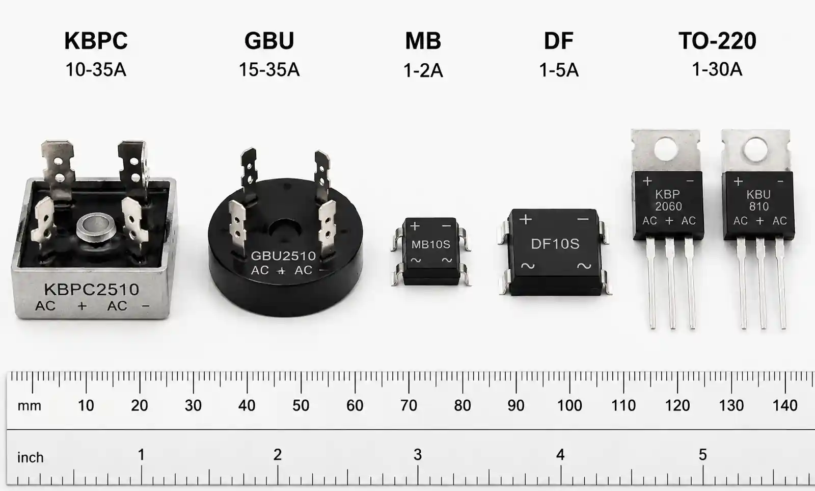
Step 5: Consider Package and Mounting Options. Through-hole bridge modules (KBPC, GBU, GBPC series) simplify assembly and provide integrated heatsink mounting in a compact package. Surface-mount packages (DIP, SOIC, SOP) save PCB space but have limited current capacity. Discrete diode implementations offer maximum flexibility for high-power designs requiring custom thermal solutions. Chassis-mount modules handle the highest power levels with bolt-down heatsink attachment.
| Application Type | Recommended Diode Type | Typical VRRM | Typical IF(AV) | Key Selection Factor |
|---|---|---|---|---|
| Industrial control 24VAC supply | Standard silicon | 200-400V | 10-35A | Cost and availability |
| Universal input SMPS (85-265VAC) | Fast recovery | 600-1000V | 1-10A | Reverse recovery time |
| Automotive 12V/24V DC-DC | Schottky | 60-100V | 10-30A | Low forward voltage drop |
| Solar inverter DC input stage | Fast recovery or SiC | 600-1200V | 20-50A | High temperature capability |
| LED driver low-voltage output | Schottky | 60-200V | 1-5A | Efficiency optimization |
This application-based selection matrix demonstrates how operating conditions dictate component choice. The "Key Selection Factor" column identifies which parameter dominates the design decision for each application category.
4. Performance Comparison: Discrete vs. Integrated Bridge Rectifiers
Engineers often face the choice between building bridge rectifiers from discrete diodes or using integrated modules. Each approach offers distinct advantages depending on design priorities.
Integrated Bridge Modules package all four diodes in a molded case with standardized pinouts (AC1, AC2, +, -). These modules simplify procurement, reduce assembly cost, minimize PCB area, and provide consistent thermal characteristics. They're available in through-hole configurations (KBPC, GBU series) with built-in heatsink mounting tabs for power applications from 1A to 50A. Surface-mount bridges (MB, DF series) serve lower-power applications up to 2-3A. The primary limitation is reduced flexibility in thermal management and inability to optimize individual diode selection.
Discrete Diode Implementation uses four individual rectifier diodes in a traditional bridge configuration. This approach allows mixing diode types (using Schottky for high-current legs and fast recovery for voltage handling), optimizing thermal distribution across the PCB by spacing diodes apart, selecting diodes with specific trr or VF characteristics for your exact application, and achieving higher total current capacity by using larger individual diode packages. The trade-offs include increased component count (4 diodes vs. 1 module), more complex PCB routing, and slightly higher assembly cost.
| Consideration | Integrated Module | Discrete Diodes |
|---|---|---|
| Component count | 1 module | 4 diodes |
| PCB area (typical 10A design) | 15-25mm² | 30-60mm² |
| Assembly cost | Lower (single placement) | Higher (4 placements) |
| Thermal design flexibility | Limited to package RθJC | Flexible spacing and heatsinking |
| Current capacity (practical limit) | Up to 50A (single module) | >100A (with proper layout) |
| Cost at 10A rating (relative) | Baseline | 0.8-1.2× |
| Failure mode | Complete bridge failure | Single diode failure (3 remain functional) |
Based on design experience, integrated modules make sense for general-purpose applications where current requirements fit standard module ratings, cost and time-to-market are priorities, and PCB space is constrained. Discrete implementations are preferred when current exceeds 35-40A (requiring parallel modules or larger discrete diodes), thermal management demands distributed heat dissipation, or specific diode characteristics (mixed Schottky and fast recovery) optimize performance.

5. Design Considerations and Common Pitfalls
Even experienced engineers encounter issues with bridge rectifier implementation. Understanding these common failure modes improves first-pass design success.
Inadequate Inrush Current Protection: At power-on, discharged filter capacitors draw surge currents that can exceed steady-state current by 20-50×. A 10A power supply might see 200-300A inrush peaks lasting several milliseconds. Standard rectifiers can typically handle brief surges of 10× their rated current, but repeated cycling or marginal designs cause cumulative damage. Solutions include NTC thermistors in series with AC input (limiting inrush to 10-30A), active inrush limiting circuits for higher power levels, soft-start circuitry that gradually charges filter capacitors, or selecting rectifiers with high IFSM (surge current) ratings—typically 10-20× the IF(AV) rating for a 60Hz half-cycle.
Insufficient Voltage Derating: Specifying VRRM exactly matching peak AC voltage leaves no margin for line transients, voltage spikes from inductive switching, or component tolerance variation. A common mistake is selecting 400V diodes for 230VAC input because peak voltage is 325V. In reality, line voltage can reach 250-265VAC during high-line conditions (peak of 370V), and transient overvoltage events can add another 50-100V. A 600V or 800V VRRM rating provides proper margin. For high-reliability applications, maintain at least 2× derating on VRRM.
PCB Layout Errors: Poor layout creates several failure mechanisms. Placing filter capacitors far from rectifier outputs increases trace inductance, causing voltage ringing and potentially exceeding VRRM during fast transient events. Inadequate copper area under rectifiers or insufficient thermal vias to internal ground planes prevents proper heat dissipation. Routing high-frequency switching currents through the rectifier circuit couples noise into the AC input. Best practices include placing bulk capacitors within 10-15mm of rectifier DC outputs, using at least 2oz copper for rectifier power traces, implementing thermal vias (0.3mm diameter, 1mm spacing) under each diode junction, and separating noisy switching circuits from rectifier/input filter sections.
Ignoring Reverse Leakage Current at High Temperature: Diode reverse leakage current approximately doubles for every 10°C temperature increase. At 125°C junction temperature, leakage may reach 100-500μA per diode—significant in precision applications. This affects standby power consumption in power supplies, can discharge hold-up capacitors in battery backup systems, and introduces measurement errors in high-impedance sensing circuits. If your application is sensitive to leakage, specify maximum IR at expected junction temperature, not just at 25°C.
Inadequate Consideration of Ripple Frequency: Bridge rectifiers produce DC output with ripple at twice the input frequency—100Hz for 50Hz mains, 120Hz for 60Hz. Higher ripple frequency allows smaller filter capacitors for the same output ripple voltage. When designing switching supplies with line-frequency front ends, remember that the bulk capacitor must store energy for the entire half-cycle period (10ms for 50Hz, 8.3ms for 60Hz). Undersizing this capacitor causes excessive ripple and increased rectifier peak current stress.
6. Supply Chain and Sourcing Considerations
Bridge rectifier availability and supply chain characteristics significantly impact product lifecycle planning.
Supplier Landscape: The bridge rectifier market is well-served by multiple manufacturers including Vishay, ON Semiconductor, Diodes Incorporated, Micro Commercial Components (MCC), and Bourns. This competitive landscape generally ensures good availability and reasonable pricing. However, specific high-current modules or specialized fast-recovery types may have limited second sources, potentially creating supply risk for high-volume production.
Standard vs. Custom Solutions: For most applications, catalog parts meet requirements and offer the best balance of cost and availability. Standard bridge modules (KBPC series, GBU series, MB series) are manufactured in high volume with excellent inventory depth at major distributors. Custom or application-specific integrated circuits may optimize BOM cost in very high volumes (>100k units annually) but increase qualification time and supply chain risk.
Lead Time and MOQ Considerations: Commodity bridge rectifiers typically maintain 8-16 week standard lead times from manufacturers, with distributor stock providing immediate availability for common parts. Specialized components (SiC Schottky bridges, high-voltage fast recovery modules) may extend to 16-24 weeks. Minimum order quantities from distributors range from 1-50 pieces for standard types. Direct manufacturer orders typically require 500-5000 piece MOQs depending on package and current rating.
| Sourcing Factor | Commodity Rectifiers (<10A) | High-Current Modules (>25A) | Specialty Types (SiC, Ultra-fast) |
|---|---|---|---|
| Typical distributor stock depth | High (>10k units) | Medium (1-5k units) | Low (100-500 units) |
| Number of qualified sources | 5-8 manufacturers | 3-5 manufacturers | 1-3 manufacturers |
| Standard lead time | 8-12 weeks | 12-16 weeks | 16-24 weeks |
| Price volatility | Low | Low-Medium | Medium-High |
| Obsolescence risk | Very Low | Low | Medium |
Alternative Sourcing Strategy: For designs requiring >10k units annually, qualify at least two manufacturers for critical bridge rectifiers. Parametric equivalence is straightforward since datasheets standardize specifications. When designing, avoid specifying proprietary package types that lock you to a single vendor. Standard packages (KBPC, GBU, DIP, SOIC) maintain broad multi-source options.
Counterfeit Risk: Bridge rectifiers, particularly popular part numbers like KBPC3510 or GBU8J, occasionally appear in counterfeit form through unauthorized distribution channels. These parts may use substandard die, inadequate thermal interfaces, or remarked lower-grade components. For production, source bridge rectifiers exclusively from authorized distributors (Digi-Key, Mouser, Arrow, Avnet) or direct from manufacturers. Require lot traceability documentation for high-reliability applications.
7. FAQ
What is the difference between bridge rectifiers and full-wave center-tap rectifiers?
Both circuits provide full-wave rectification, but bridge rectifiers use four diodes without requiring a center-tapped transformer, while center-tap designs need only two diodes but require a transformer with center-tapped secondary winding. Bridge rectifiers are more economical for most applications since center-tap transformers cost significantly more than standard transformers. The bridge configuration also delivers twice the output voltage for a given transformer secondary voltage, making it preferred except in very low voltage applications where the two-diode voltage drop (1.4-2.0V) of center-tap designs offers an advantage.
How do I calculate the required filter capacitor size?
For a bridge rectifier with capacitor-input filter, use the approximation: C ≥ (IDC × t) / ΔVDC, where t is the discharge time (approximately half the ripple period—5ms for 100Hz, 4.15ms for 120Hz) and ΔVDC is acceptable peak-to-peak ripple voltage. For a 5A load with 1V ripple at 100Hz: C ≥ (5A × 0.005s) / 1V = 25,000μF. In practice, use 30,000-40,000μF to account for capacitor tolerance and aging. Remember that larger capacitance increases inrush current, requiring appropriate surge protection.
Can I parallel bridge rectifiers to increase current capacity?
Yes, but current sharing depends on matching VF characteristics. Diodes with identical VF at operating current will share current evenly. Typical VF variation between production lots ranges from 50-150mV, causing 10-25% current imbalance. For reliable parallel operation, select modules from the same production lot, maintain matched thermal environments (equal heatsink contact and airflow), and derate total capacity to 1.6-1.8× rated current of a single module rather than simply multiplying. For currents above 50A, discrete high-current diodes with individual thermal management often provide better cost and reliability than paralleled modules.
What testing should I perform to validate bridge rectifier selection?
Critical validation tests include thermal imaging under maximum load to verify junction temperature remains below 125°C with appropriate margin, inrush current measurement at cold start to confirm surge rating adequacy and verify NTC thermistor or soft-start effectiveness, output ripple measurement across load range and input voltage conditions, reverse voltage stress testing at 80-90% of VRRM to identify any marginal voltage derating, and long-term thermal cycling (25°C to 85°C, 100+ cycles) for high-reliability applications. If your design operates in high-vibration environments, shock and vibration testing validates solder joint and heatsink mounting integrity.
How do I select between silicon and silicon carbide (SiC) bridge rectifiers?
Silicon carbide rectifiers offer lower switching losses, higher temperature operation (up to 175-200°C junction temperature), and effectively zero reverse recovery time, but cost 3-5× more than silicon equivalents. SiC justifies its premium in high-frequency applications (>100kHz) where switching losses dominate, high-temperature environments (>125°C ambient), or efficiency-critical designs where every percentage point matters (solar inverters, EV chargers). For conventional 50/60Hz line-frequency rectification, silicon fast-recovery diodes provide the best cost-performance balance. Between 100-200kHz switching frequency, perform a total system cost analysis accounting for reduced heatsink size, smaller magnetics, and efficiency gains.
What causes bridge rectifier failure and how can I prevent it?
Common failure modes include thermal overstress from inadequate heatsinking or underrated current capacity, voltage spike damage when VRRM is exceeded due to transients or insufficient derating, repeated inrush current stress causing wire bond fatigue, and solder joint cracking from thermal cycling or mechanical stress. Prevention strategies include derating current to 60-80% of rated capacity for continuous operation, maintaining 1.5-2× voltage margin on VRRM, implementing inrush limiting (NTC thermistor or active circuit), ensuring proper thermal design with adequate copper area and heatsinking, and using thermal vias to internal planes for surface-mount implementations. In high-reliability applications, monitor rectifier temperature during qualification testing and verify it remains below 100°C junction temperature.
8. Conclusion and Recommended Next Steps
Bridge rectifier selection directly impacts power supply efficiency, reliability, and total system cost. The fundamental decisions—integrated module versus discrete diodes, standard silicon versus Schottky versus fast recovery, and package selection for thermal management—should be driven by your specific application requirements rather than defaulting to familiar components.
For line-frequency applications with moderate current requirements (<15A), integrated bridge modules offer the best balance of cost, simplicity, and reliability. High-current designs (>25A) benefit from discrete diode implementations that distribute thermal load and allow custom heatsink configurations. Low-voltage outputs (<24VDC) almost always justify Schottky rectifiers despite higher cost due to significant efficiency improvements from reduced conduction loss.
Before finalizing your selection, verify that junction temperature remains below 125°C under worst-case conditions, VRRM provides at least 1.5× margin above peak operating voltage including transients, inrush current protection adequately limits surge stress, and your thermal design accounts for actual operating environment (ambient temperature, airflow, heatsink effectiveness).
To move forward with your bridge rectifier design, download datasheets for candidate components from at least two manufacturers to ensure multi-source availability, calculate power dissipation and thermal performance under your specific operating conditions, prototype your design with thermal testing to validate junction temperature calculations, and establish second-source qualification for production volumes exceeding 10k units annually.