




Capacitor Selection Guide: Ceramic, Electrolytic, and Tantalum Compared
Table of Contents
Introduction
Choosing the right capacitor is far more than matching capacitance values. Ceramic, electrolytic, and tantalum each bring distinct strengths and weaknesses that directly affect circuit performance, reliability, and cost. Drawing from hundreds of power‑supply reviews and field failure analyses, this guide cuts through datasheet hype to deliver actionable, engineering‑grounded advice. Whether you design switching regulators, signal paths, or embedded systems, understanding these three families will prevent costly redesigns and field returns.
Understanding Capacitor Types
Ceramic Capacitors (MLCC)
Multi‑Layer Ceramic Capacitors (MLCCs) dominate modern electronics because of their tiny size and outstanding high‑frequency response. They stack thin ceramic dielectric layers between metal electrodes to achieve high capacitance density in small packages.
Their key advantage is extremely low ESR – typically 1‑50 mΩ – making them ideal for high‑frequency decoupling and fast transient support. Class I dielectrics (C0G/NP0) offer near‑zero temperature drift (±30 ppm/°C), while Class II (X7R, X5R) provide higher capacitance but with voltage‑ and temperature‑dependent stability.
The hidden trap: DC bias voltage coefficient. High‑capacitance X7R parts can lose 50‑80 % of nominal capacitance at rated voltage. Always derate voltage ratings by 2‑3× to retain effective capacitance.
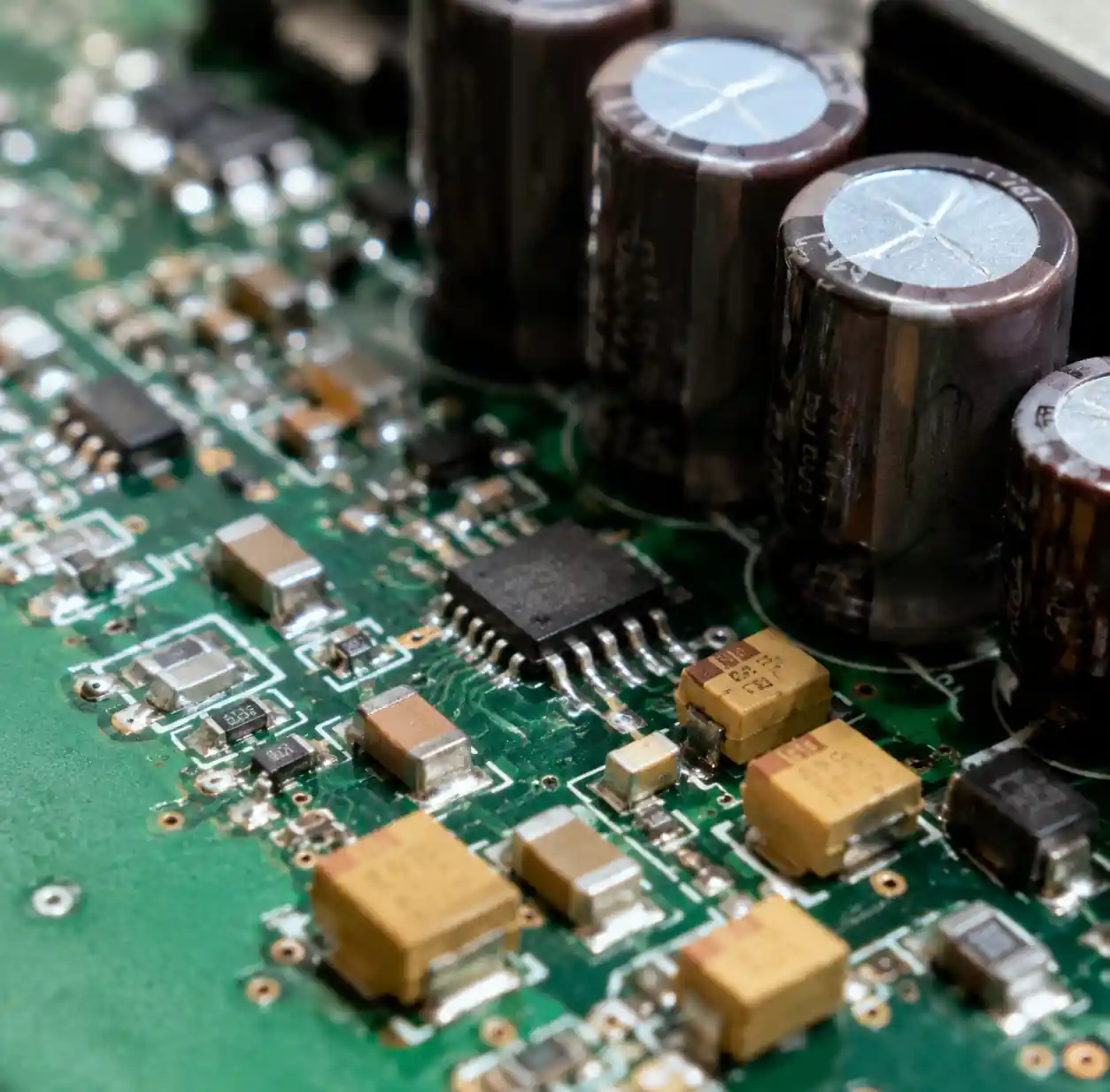 Three different capacitor types - ceramic, electrolytic, and tantalum capacitors displayed on circuit board
Electrolytic Capacitors
Aluminum electrolytics are the workhorse for bulk energy storage, offering capacitance from 1 µF to tens of thousands of µF at the lowest cost per µF. Their thin oxide dielectric, grown on etched aluminum foil, enables this density.
The trade‑offs are significant: they are polarised (reverse voltage causes catastrophic failure), ESR ranges from 100 mΩ to several ohms, and the liquid electrolyte limits lifetime – typically 2 000‑5 000 hours at high temperature. Ripple current rating is critical; exceeding it raises core temperature, and every 10 °C rise halves expected life. This Arrhenius‑based relationship has been validated in accelerated tests on thousands of production units.
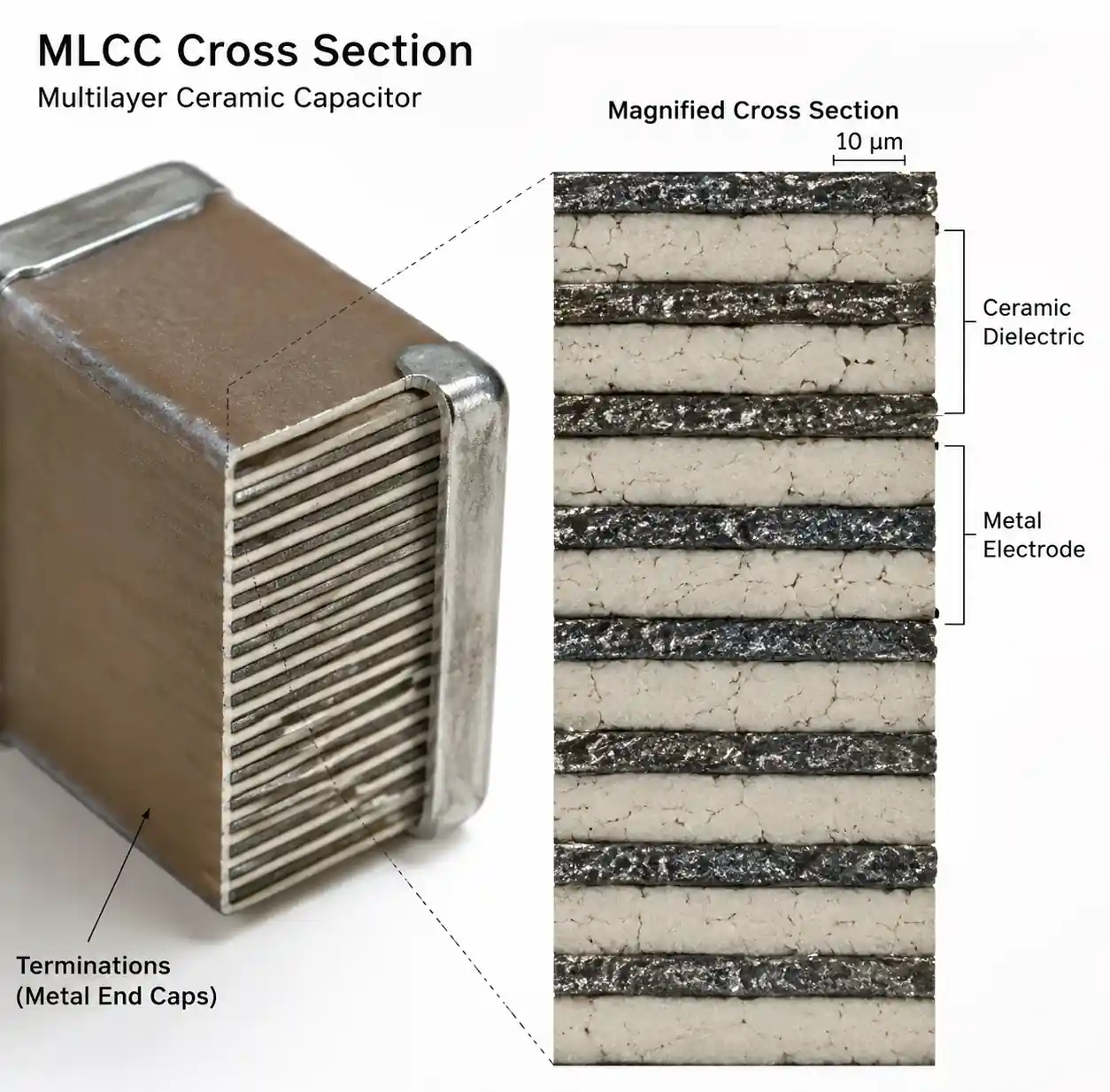 Multi-layer ceramic capacitor internal structure showing dielectric layers
Tantalum Capacitors
Tantalum capacitors bridge the gap, offering higher density than ceramics with better stability than aluminium electrolytics. Using tantalum pentoxide as the dielectric, they maintain capacitance over time and temperature.
ESR falls between ceramics and electrolytics – roughly 100 mΩ to 1 Ω – suitable for mid‑frequency filtering. Their reliability is excellent; they show minimal degradation over decades. However, their failure mode is severe: overvoltage or end‑of‑life can cause a short circuit, sometimes with ignition due to exothermic reaction with manganese dioxide. Polymer tantalums or series resistance are recommended for safety‑critical applications.
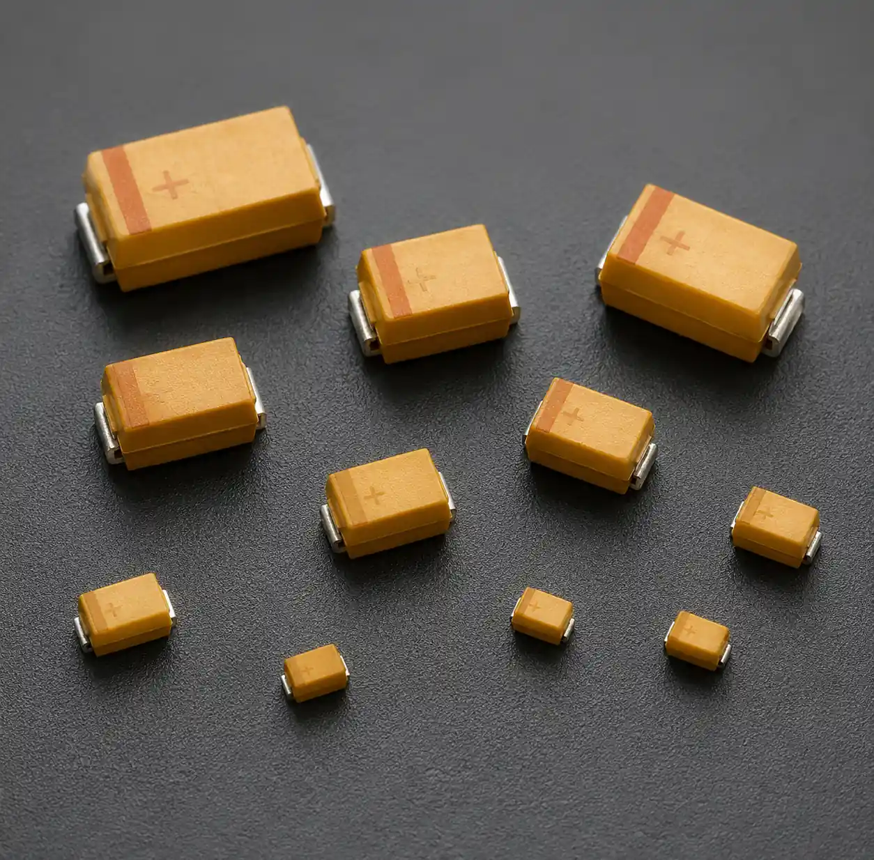 Tantalum capacitor showing compact SMD package and color coding
Key Performance Comparison
The table below summarises typical commercial specifications:
| Parameter | Ceramic (MLCC) | Aluminum Electrolytic | Tantalum |
|---|---|---|---|
| Capacitance Range | 1pF – 100µF | 0.1µF – 100,000µF | 0.1µF – 1,500µF |
| Voltage Rating | 6.3V – 3kV | 6.3V – 550V | 2.5V – 50V |
| ESR (typical) | 1‑50mΩ | 100mΩ – 5Ω | 100mΩ – 1Ω |
| Operating Temp | ‑55°C to +150°C | ‑55°C to +105°C | ‑55°C to +125°C |
| Lifetime | Unlimited | 2,000‑10,000 hrs | 50,000+ hrs |
| Self‑Resonance | High (>10MHz) | Low (100kHz‑1MHz) | Medium (1‑10MHz) |
| Polarity | Non‑polarised | Polarised | Polarised |
Hybrid approaches are almost always best: bulk electrolytic + mid‑frequency tantalum/ceramic + high‑frequency MLCC in a single power rail.
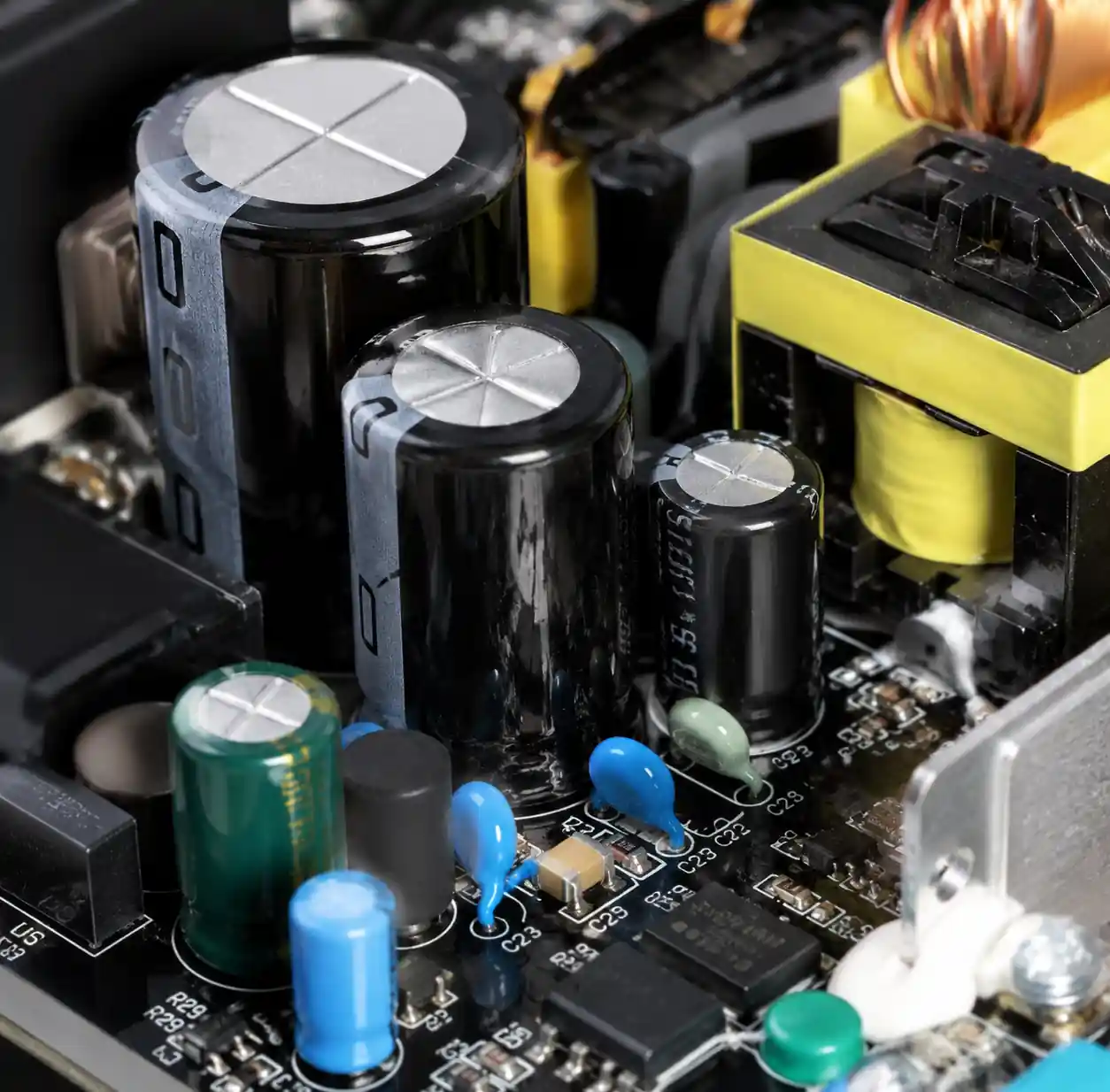 Power supply circuit showing mixed capacitor types for different frequency ranges
Critical Selection Parameters
ESR and Impedance Characteristics
ESR determines transient current capability. In switching regulators, output ripple voltage is simply V_ripple = I_ripple × ESR. What datasheets often hide is ESR variation with frequency and temperature. Aluminium electrolytics can show 5‑10× higher ESR at ‑40 °C than at 25 °C – a common cause of cold‑start instability in automotive designs.
Ceramics behave differently: impedance is capacitive at low frequencies and inductive (ESL‑dominated) at high frequencies. The self‑resonant frequency marks the minimum impedance point; above it, the capacitor is effectively an inductor and loses decoupling ability.
Voltage and Temperature Effects
Voltage coefficient in X7R ceramics is a prime pitfall. Measured data for a typical 10 µF, 25 V X7R part:
| Applied Voltage | Remaining Capacitance | Effective Value |
|---|---|---|
| 0V | 100% | 10.0µF |
| 5V (20% rated) | 85% | 8.5µF |
| 12.5V (50% rated) | 55% | 5.5µF |
| 18.75V (75% rated) | 35% | 3.5µF |
| 25V (100% rated) | 20% | 2.0µF |
Thus a 10 µF capacitor at rated voltage delivers only 2 µF in practice. Professional designers select 2‑3× higher voltage ratings or parallel multiple devices. Temperature coefficients also matter: C0G/NP0 is stable (±30 ppm), X7R varies ±15 %, Y5V can change from +22 % to ‑82 % over temperature.
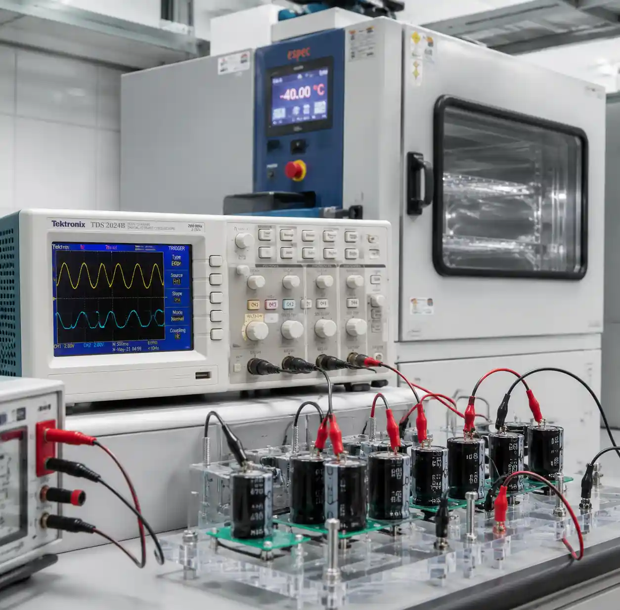 Capacitors under temperature test showing measurement equipment
Reliability and Lifetime
Aluminium electrolytics follow the Arrhenius model: lifetime doubles for each 10 °C reduction in core temperature. A 2 000‑hour, 105 °C capacitor lasts ~16 000 hours at 65 °C – critical for MTBF calculations.
Tantalums have minimal wear‑out; their primary failure is voltage‑stress breakdown. Derated to 50 % of rated voltage, they can achieve <0.1 FIT (failures per billion hours). Ceramics are essentially immortal under normal conditions, failing only from mechanical cracking or manufacturing defects.
Application‑Specific Selection
- Power supply output filtering: Combine bulk aluminium electrolytic (low‑frequency ripple and hold‑up) with ceramics (high‑frequency noise). Place ceramics close to the load to minimise trace inductance.
- Decoupling: Ceramics are the go‑to due to low ESR and high self‑resonance. Modern practice favours one large (10‑22 µF) MLCC close to the IC rather than multiple values, which can introduce anti‑resonance peaks.
- Audio signal paths: Use C0G/NP0 or film capacitors. Class II ceramics exhibit piezoelectric effects – I have measured 10‑50 mV of audio noise from X7Rs near speakers or mechanical stress points.
- Timing/oscillators: Only C0G/NP0 or film capacitors – their stable temperature and zero voltage coefficient ensure accurate frequency.
- Automotive/high‑reliability: Polymer aluminium or polymer tantalum offer the best balance. Standard liquid electrolytics struggle with wide temperature ranges and vibration; specify 125 °C‑rated parts even if ambient is lower.
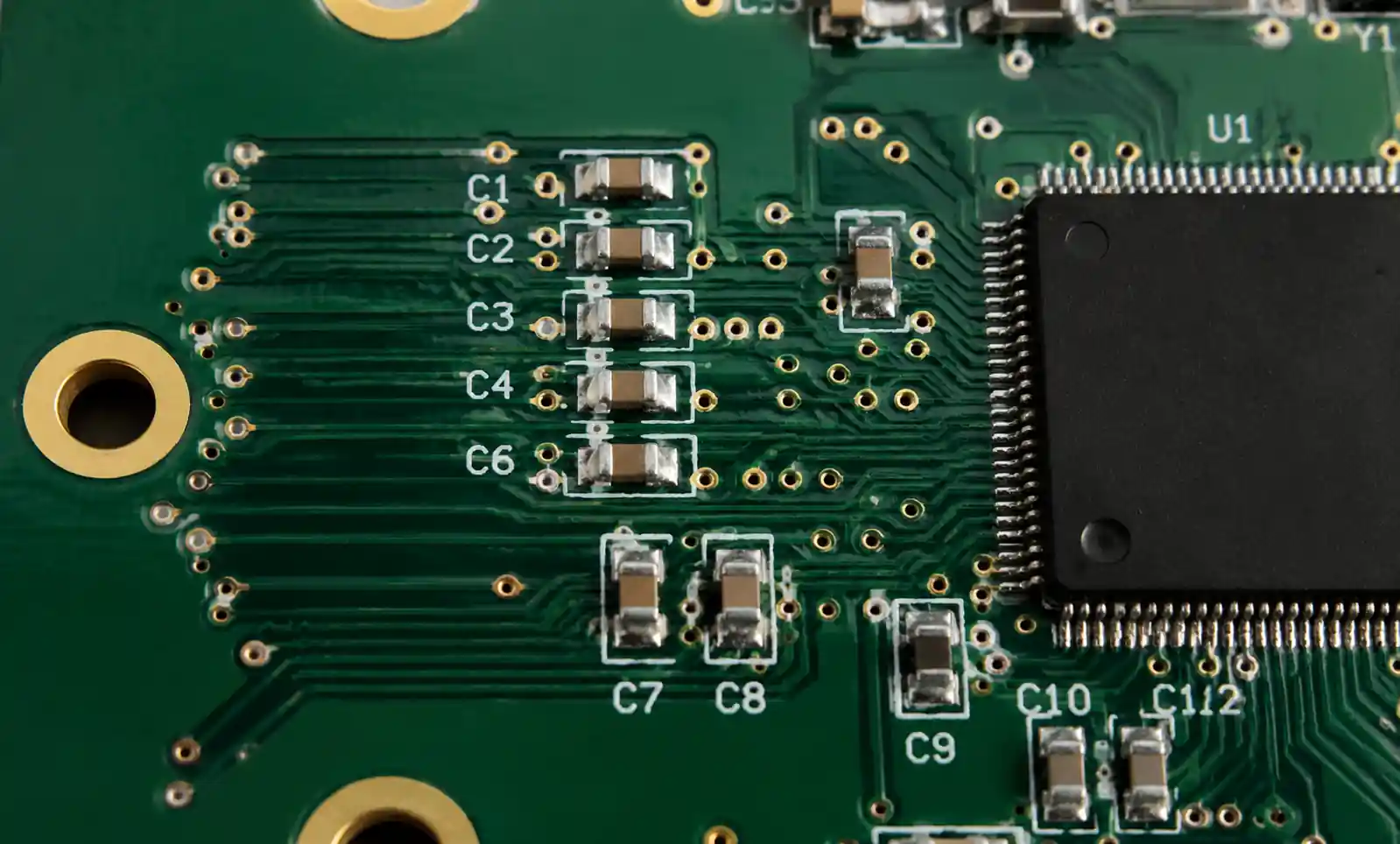 PCB layout showing optimal ceramic capacitor placement near IC power pins
Common Mistakes to Avoid
- Ignoring DC bias: Always consult derating curves for ceramic capacitors. Do not rely on nominal capacitance at operating voltage.
- Underestimating ripple current: In switching supplies, calculate RMS ripple accurately and select electrolytics with ≥1.5× rating (2× for high‑reliability).
- Poor PCB layout: A 10‑15 mm trace between capacitor and IC can reduce decoupling effectiveness by 50 % at 100 MHz due to added inductance.
- Neglecting thermal derating: Component self‑heating plus proximity to hot parts can raise capacitor temperature 20‑40 °C above ambient. Measure or simulate actual conditions.
- Tantalum overvoltage: Derate to 50 % of rated voltage. Add series resistance or switch to polymer types for transient‑prone applications.
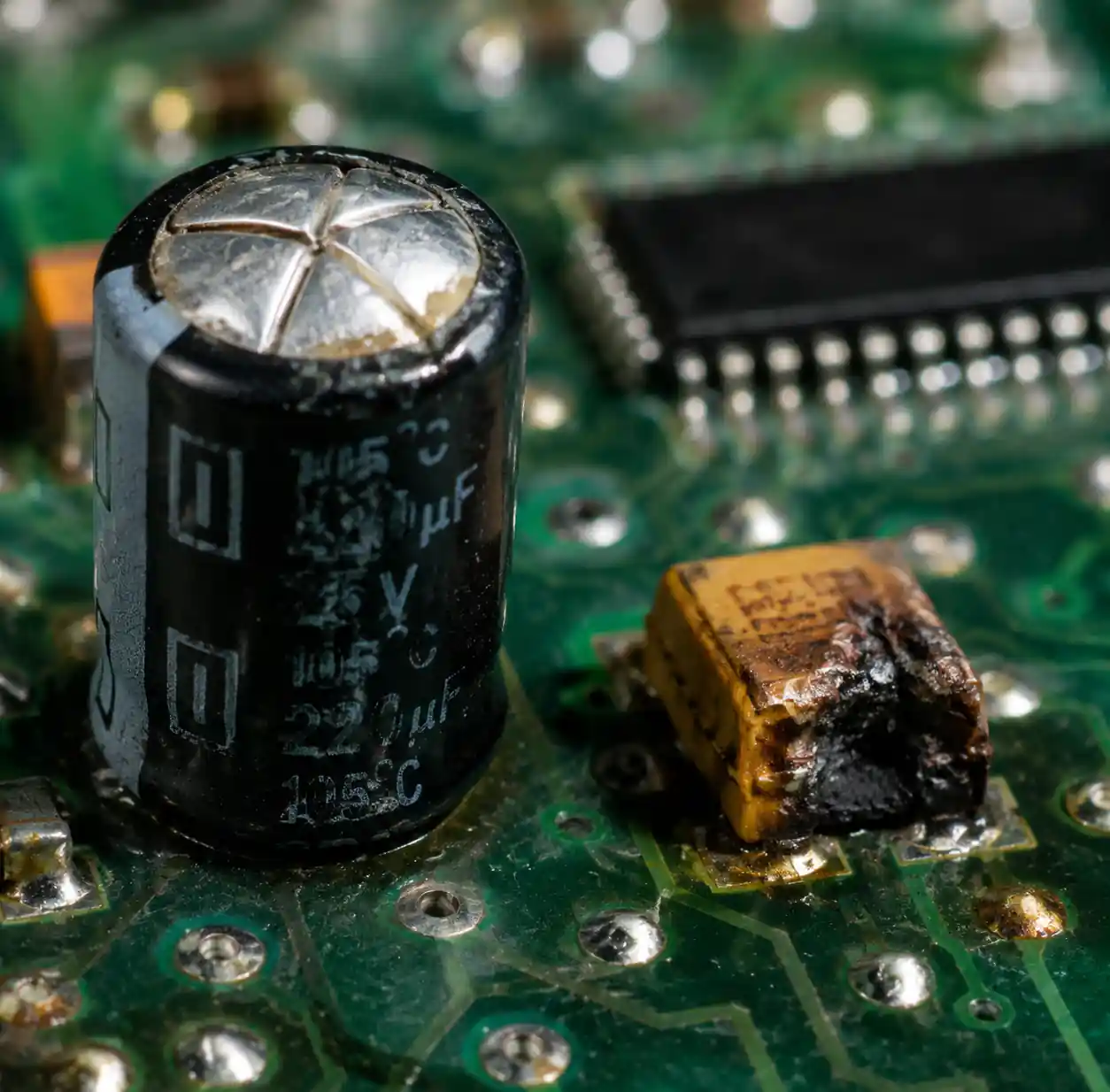 Failed capacitors showing bulging electrolytic and damaged tantalum
Cost vs Performance Analysis
| Capacitor Type | Relative Cost (10µF, 16V) | Best Value Sweet Spot |
|---|---|---|
| Ceramic (X7R) | 1.0x baseline | Standard decoupling, high volume |
| Aluminum Electrolytic | 0.3‑0.5x | Bulk storage, cost‑sensitive |
| Tantalum (MnO₂) | 3‑5x | Compact, reliable, mid‑frequency |
| Polymer Tantalum | 5‑8x | High reliability, safety‑critical |
| Polymer Aluminum | 2‑3x | Long life, automotive, high ripple |
Lowest component cost does not always mean lowest system cost. A $0.10 electrolytic may need field replacement, while a $0.30 polymer lasts the product lifetime. For consumer goods with short warranties, aluminium makes sense; for industrial/medical/automotive, premium capacitors reduce warranty claims and protect brand reputation.
FAQ
Q: Can I parallel different capacitor types?
Yes – standard practice. Combine bulk electrolytic with ceramics for high‑frequency. Verify that total ESR/ESL meets requirements across the full frequency range.
Q: How do I estimate effective capacitance of an X7R at operating voltage?
Use manufacturer derating curves. As a rule of thumb, expect 50‑60 % loss at 50 % rated voltage and 70‑80 % loss at rated voltage.
Q: Why do ceramic capacitors crack?
PCB flexing during assembly or thermal cycling. Use flexible‑termination types, avoid board edges/screw holes, and control reflow cooling rates.
Q: Why do tantalums sometimes catch fire?
Overvoltage causes dielectric breakdown; the MnO₂‑tantalum reaction is exothermic. Use 50 % voltage derating, series resistance, or polymer tantalums.
Q: How long do aluminium electrolytics really last?
Under rated conditions, specified lifetime (e.g., 2 000 h). Reduce temperature by 20 °C to extend to >20 000 h. Use L₂ = L₁ × 2^((T₁‑T₂)/10).
Q: One large or several small decoupling capacitors?
Modern best practice favours one well‑placed 10‑22 µF MLCC over multiple values, which can create anti‑resonance. Keep lead/trace length minimal in either approach.
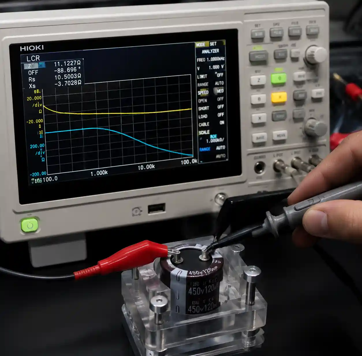 Oscilloscope measuring capacitor ESR and impedance characteristics
Conclusion
Effective capacitor selection hinges on understanding the fundamental trade‑offs: ceramics excel at high frequencies but suffer from voltage bias; electrolytics give maximum µF per dollar but have finite life; tantalums offer a reliable middle ground at higher cost. Successful designs combine all three – bulk electrolytics for energy storage, tantalums for mid‑frequency filtering, and ceramics for high‑frequency decoupling. Always verify performance under actual conditions: voltage derating, temperature, and frequency response. Compute ripple current, account for DC bias, and provide thermal margin. These disciplined practices will prevent the field failures that plague rushed designs and ensure robust, long‑lasting products.
