


Buck Converter: Working Principles, Topologies, Design Considerations, and Applications
A Buck Converter (step-down switching regulator) is one of the most fundamental and widely used DC-DC power conversion topologies. By leveraging high-frequency switching and energy storage components, it achieves high efficiency and superior thermal performance compared to linear regulators. This article provides a deep engineering-level analysis of buck converters, covering operating principles, topology variations, key design equations, control strategies, and practical implementation challenges.
Table of Contents
- Introduction to Buck Converters
- Operating Principle and Switching Cycle
- Key Components and Selection Criteria
- Buck Converter Topologies
- Design Equations and Engineering Insights
- Control Methods and Stability
- Buck Converter vs Linear Regulator
- Typical Applications
- Common Design Issues and Solutions
- FAQ
Introduction to Buck Converters
A Buck Converter is a non-isolated DC-DC converter designed to efficiently step down a higher input voltage to a lower output voltage. Unlike linear regulators, it does not dissipate excess voltage as heat but instead transfers energy through switching and storage elements.
Key characteristics:
- High efficiency (typically 85%–95%)
- PWM-based control
- Energy transfer via inductor
- Output voltage controlled by duty cycle
Operating Principle and Switching Cycle
A buck converter operates through periodic switching, typically controlled by PWM.
Switching States
1. ON State (Switch Closed)
- Input voltage is applied across the inductor
- Inductor current increases linearly
- Energy is stored in the magnetic field
2. OFF State (Switch Open)
- Inductor releases stored energy
- Current flows through the freewheeling path
- Inductor current decreases
Figure 1: Buck Converter Switching Waveforms
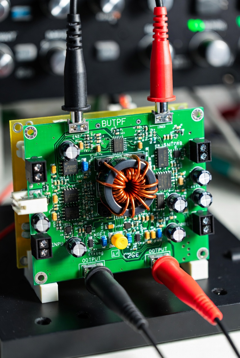
Suggested content: Inductor current waveform, switch node voltage, PWM signal
Key Components and Selection Criteria
1. MOSFET (Switch)
- Low Rds(on) reduces conduction losses
- Low gate charge (Qg) reduces switching losses
- Trade-off between efficiency and switching speed
2. Inductor
- Determines ripple current and conduction mode
- Avoid saturation
- Typical ripple design: 20–40% of rated current
3. Capacitor
- Filters output voltage ripple
- Important parameters: capacitance and ESR
4. Diode / Synchronous MOSFET
- Diode: simple but less efficient
- MOSFET: higher efficiency, requires control
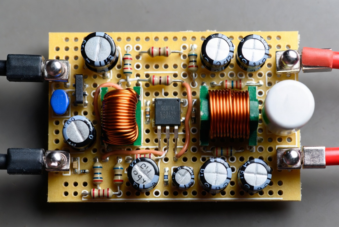
Figure 2: Basic Buck Converter Circuit
Buck Converter Topologies
Non-Synchronous Buck
- Uses diode for freewheeling
- Lower cost, lower efficiency
Synchronous Buck
- Uses MOSFET instead of diode
- Higher efficiency, especially at low voltage
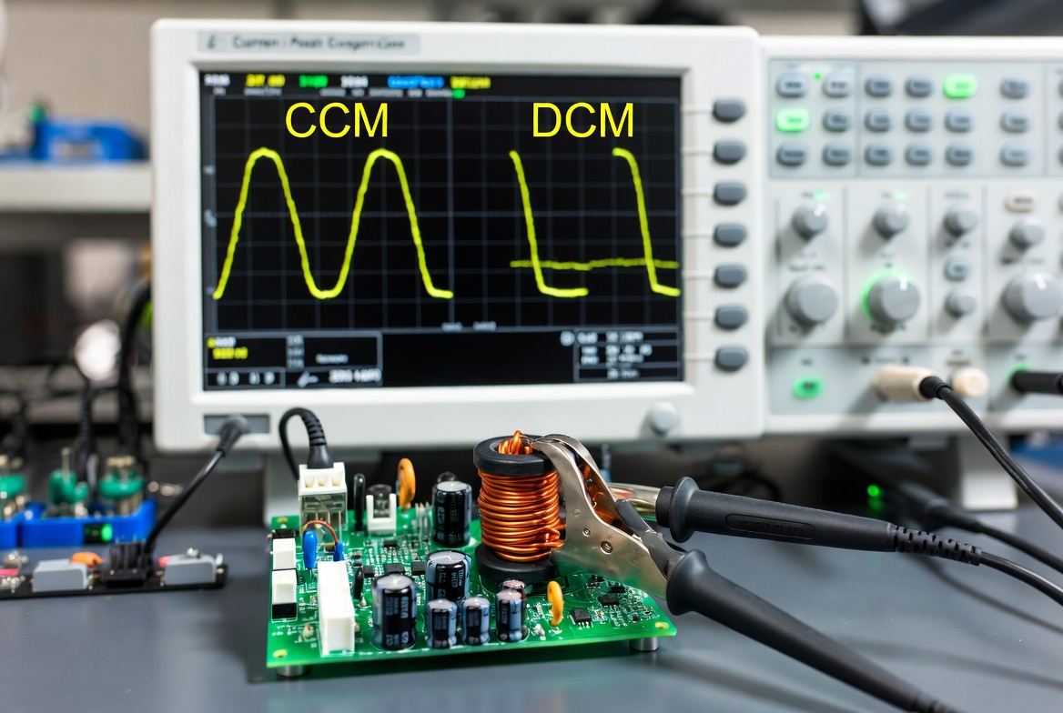
Continuous Conduction Mode (CCM)
- Inductor current never reaches zero
- Lower ripple and higher efficiency
Discontinuous Conduction Mode (DCM)
- Inductor current drops to zero
- Suitable for light loads
- Higher ripple and EMI complexity
Multiphase Buck
- Multiple interleaved phases
- Reduced ripple and improved thermal performance
Figure 3: CCM vs DCM Inductor Current
Design Equations and Engineering Insights
Output Voltage
[ V_{out} = D \cdot V_{in} ]
Inductor Current Ripple
[ \Delta I_L = \frac{(V_{in} - V_{out}) \cdot D}{L \cdot f} ]
Output Voltage Ripple
[ \Delta V_{out} \approx \frac{\Delta I_L}{8 \cdot f \cdot C} ]
Control Methods and Stability
Control Techniques
- Voltage Mode Control (VMC)
- Current Mode Control (CMC)
Compensation Design
- Type II / Type III compensation
- Ensures loop stability and transient response
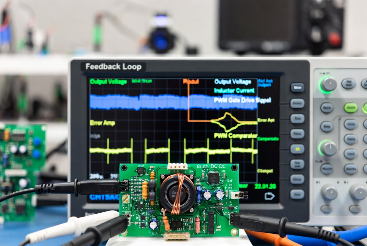
Figure 4: Control Loop and Compensation Network
Buck Converter vs Linear Regulator
| Feature | Buck Converter | Linear Regulator |
|---|---|---|
| Efficiency | High (>85%) | Low |
| Heat Generation | Low | High |
| Complexity | High | Low |
| Noise | Higher (switching noise) | Very low |
| Best Use Case | Medium to high power systems | Low-noise analog circuits |
Typical Applications
CPU Power Supplies (VRMs)
- Multiphase buck converters
- High current delivery
Battery-Powered Devices
- Smartphones, tablets
- Extends battery life
LED Drivers
- Constant current control
- High efficiency
Automotive Electronics
- 12V to 5V / 3.3V conversion
- High reliability
Embedded Systems
- Microcontrollers and IoT devices
- Stable voltage rails
Common Design Issues and Solutions
Output Voltage Ripple
Cause: High ESR or insufficient capacitance
Solution: Use low-ESR capacitors and increase capacitance
EMI Problems
Cause: Fast switching transitions
Solution: Add snubber circuits and optimize PCB layout
MOSFET Overheating
Cause: High switching losses
Solution: Use low Qg MOSFET and improve gate drive
Instability
Cause: Poor compensation design
Solution: Tune compensation network and verify with Bode plot
FAQ
Q1: Why are buck converters more efficient than linear regulators?
Because they transfer energy through switching and storage rather than dissipating excess voltage as heat.
Q2: When should a synchronous buck converter be used?
- Low output voltage (<3.3V)
- High current applications
- Efficiency-critical systems
Q3: Is higher switching frequency always better?
No. Higher frequency reduces size but increases switching loss.
Q4: How to distinguish CCM and DCM?
- CCM: Inductor current never reaches zero
- DCM: Inductor current reaches zero each cycle
Q5: Can a buck converter provide isolation?
No. Standard buck converters are non-isolated. Isolation requires different topologies such as flyback converters.
Conclusion
The Buck Converter is a cornerstone of modern power electronics. While its concept is straightforward, real-world implementation requires careful trade-offs between efficiency, thermal performance, EMI, and stability. Advanced systems increasingly rely on synchronous and multiphase designs to meet demanding performance requirements.