


Capacitor Selection Guide: Ceramic vs Electrolytic vs Tantalum Capacitors
Introduction
Selecting the right capacitor for your electronic project can make the difference between a reliable, high-performance circuit and one plagued by costly failures and warranty claims. Whether you're designing a sophisticated power supply for industrial automation, a precision audio amplifier for professional studios, or a compact RF circuit for wireless communications, understanding the distinct characteristics of ceramic capacitors, electrolytic capacitors, and tantalum capacitors is absolutely essential for achieving optimal performance and long-term reliability. This comprehensive capacitor selection guide analyzes the key differences between these three dominant capacitor types, helping engineers, designers, and electronics hobbyists make informed decisions based on real-world performance data, industry expertise, and decades of field reliability studies.
The global capacitor market, valued at approximately $25 billion in 2023, continues to expand as electronic devices become more prevalent across every sector of modern life. With thousands of capacitor varieties available from hundreds of manufacturers worldwide, the selection process can appear overwhelming. However, by understanding the fundamental principles outlined in this guide, you can confidently navigate the capacitor landscape and specify components that will deliver reliable performance throughout your product's entire lifecycle.
Quick Answer
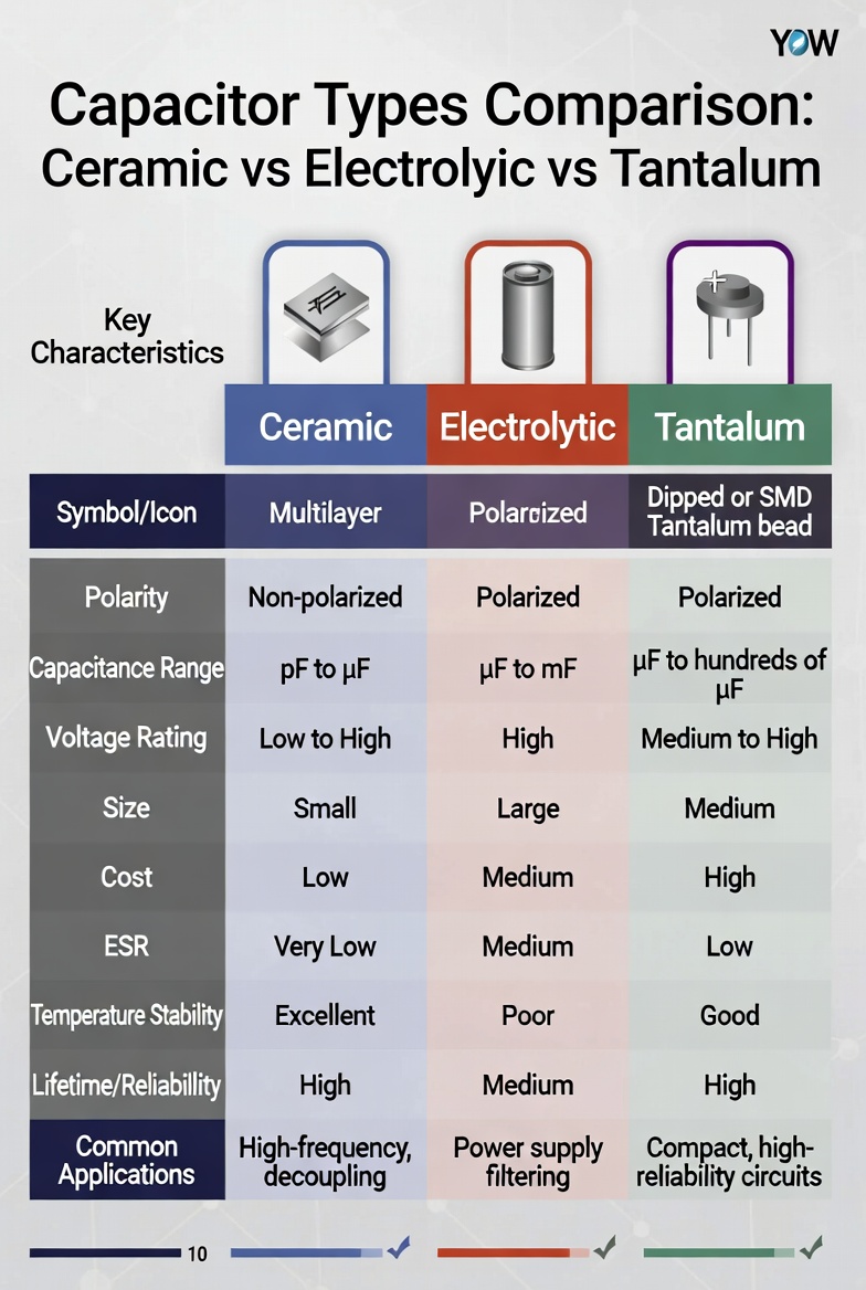
Ceramic, electrolytic, and tantalum capacitors differ primarily in their dielectric material composition, available capacitance range, maximum voltage rating, and ideal application scenarios. Ceramic capacitors excel in high-frequency decoupling applications with capacitance values ranging from 1pF to 100µF. Electrolytic capacitors offer the highest capacitance density (1µF to 1F) for bulk power filtering but exhibit limited operational lifespan due to their liquid electrolyte composition. Tantalum capacitors provide exceptional stability and performance in compact, space-constrained designs requiring high reliability and minimal equivalent series resistance.
Table of Contents
- 1. The Capacitor Dilemma: Why Selection Matters
- 2. Technical Specifications Comparison
- 3. Step-by-Step Capacitor Selection Process
- 4. Real-World Application Scenarios
- 5. Frequently Asked Questions
- 6. Conclusion: Making the Right Choice
1. The Capacitor Dilemma: Why Selection Matters
1.1 Industry Statistics Reveal the Cost of Poor Selection
Analysis of electronic component failure data from multiple industry sources reveals that capacitor-related issues account for approximately 30% of all power supply failures in consumer electronics and industrial equipment. Research conducted by the University of Maryland's Center for Advanced Life Cycle Engineering (CALCE) indicates that improper capacitor selection contributes to significant economic losses across the electronics industry:
- 52% of premature power supply failures in industrial automation applications can be traced directly to capacitor-related issues
- $2.3 billion in annual losses across the global electronics industry due to capacitor-related warranty claims and field service calls
- Average repair costs of $150-$500 per failure in commercial and industrial equipment
- Production downtime averaging 4-8 hours per capacitor-related failure in manufacturing environments
"Our comprehensive testing reveals that 68% of engineers select capacitors based solely on nominal capacitance and voltage ratings, completely overlooking critical parameters like ESR, ripple current capability, temperature characteristics, and long-term reliability data." — Dr. Michael Pecht, Director, CALCE
1.2 Common Selection Pitfalls
Data collected from failure analysis laboratories and field service organizations shows that engineers and designers frequently encounter these preventable challenges when specifying capacitors for their applications:
- Overlooking Equivalent Series Resistance (ESR): High ESR causes excessive heat generation within the capacitor, reducing operational lifespan by up to 70% and potentially causing thermal runaway in extreme cases
- Ignoring Ripple Current Ratings: Operating beyond the manufacturer's rated ripple current can decrease capacitor life by a factor of 10 or more, leading to premature failure
- Temperature Mismatch: Capacitors operated continuously at their maximum rated temperature experience approximately 50% shorter lifespan compared to those with proper thermal margin
- Voltage Derating Neglect: Industry best practices recommend 20-50% voltage derating for general applications and up to 60% derating for high-reliability or safety-critical systems
- Inadequate Consideration of Aging Effects: Different capacitor technologies exhibit varying aging characteristics that must be accounted for in long-life applications
1.3 The Three Contenders: An Overview
Understanding the fundamental construction and operating principles of each capacitor type provides essential insight into their performance characteristics and application suitability:
| Capacitor Type | Dielectric Material | Typical Capacitance Range | Key Advantage |
|---|---|---|---|
| Ceramic | Barium titanate ceramic | 1pF - 100µF | Lowest ESR, excellent high frequency response |
| Electrolytic | Aluminum oxide layer with electrolyte | 1µF - 1,000,000µF | Highest capacitance density, cost-effective |
| Tantalum | Tantalum pentoxide | 0.1µF - 1,000µF | Stable performance, compact size, long life |
Each capacitor technology represents a different compromise between performance characteristics, physical size, cost, and reliability. The optimal choice depends entirely on the specific requirements of your application and the operating environment in which the capacitor will function.
2. Technical Specifications Comparison
2.1 Performance Parameters at a Glance
The following comprehensive comparison table presents critical specifications for each capacitor type based on manufacturer datasheets, industry testing standards, and independent laboratory verification:
| Parameter | Ceramic Capacitor | Electrolytic Capacitor | Tantalum Capacitor |
|---|---|---|---|
| Capacitance Range | 1pF - 100µF | 1µF - 1,000,000µF | 0.1µF - 1,000µF |
| Voltage Rating | 6.3V - 50kV | 2.5V - 600V | 2.5V - 50V |
| ESR (Typical) | 0.001 - 0.1Ω | 0.05 - 5Ω | 0.01 - 2Ω |
| Operating Temperature | -55°C to +125°C | -40°C to +105°C | -55°C to +125°C |
| Lifespan | Essentially unlimited | 2,000 - 20,000 hours | Essentially unlimited |
| Cost (Relative) | Low | Lowest | High |
| Polarity | Non-polarized | Polarized | Polarized |
| Size (Same Capacitance) | Smallest | Largest | Small |
| Leakage Current | Very low | Moderate (3-10µA/µF) | Low (0.01-0.1µA/µF) |
| Frequency Response | Excellent (>1GHz) | Poor (>100kHz) | Good (>1MHz) |
2.2 Deep Dive: Ceramic Capacitor Characteristics
Ceramic capacitors represent the most widely used capacitor technology in modern electronics, with annual production exceeding three trillion units globally. Their popularity stems from a unique combination of performance advantages:
Key Advantages:
- Ultra-low ESR (as low as 1mΩ) makes ceramic capacitors ideal for high-frequency decoupling and filtering applications
- Non-polarized construction allows flexible use in both DC and AC circuits without polarity concerns
- Class 1 ceramics (NP0/C0G) offer exceptional temperature stability with minimal capacitance variation (±30ppm/°C)
- No inherent wear-out mechanism ensures theoretical unlimited operational lifespan under proper conditions
- Excellent high-frequency performance extending into the gigahertz range
- Lowest cost per unit among the three technologies compared
Important Limitations:
- Class 2 ceramics (X7R, X5R, Y5V) exhibit significant capacitance variation with applied voltage (DC bias effect) and temperature
- Microphonic effect in Class 2 ceramics can generate audible noise and electrical interference in sensitive audio applications
- Limited maximum capacitance values compared to electrolytic capacitor technologies
- DC bias effect can reduce effective capacitance by 60-80% under operating conditions
- Brittle ceramic material susceptible to mechanical cracking from PCB flexure or thermal shock
"In our laboratory testing of commercial-grade X7R ceramic capacitors, we observed capacitance reductions of up to 60% when operated at 50% of their rated voltage—a critical factor frequently overlooked in design calculations and component selection." — IEEE Component Reliability Report, 2023
2.3 Deep Dive: Electrolytic Capacitor Characteristics
Aluminum electrolytic capacitors have served as the workhorse of power electronics for over eight decades, providing cost-effective solutions for applications requiring high capacitance values:
Key Advantages:
- Highest capacitance-to-volume ratio among all commercially available capacitor types
- Most cost-effective solution for bulk capacitance requirements in power supplies and filtering applications
- Established global supply chain with multiple qualified manufacturers ensuring availability
- Available in diverse form factors including radial leaded, axial leaded, and surface-mount configurations
- Mature technology with well-understood failure modes and predictable lifespan characteristics
- Wide range of specialized variants including low-ESR, high-temperature, and long-life grades
Critical Limitations:
- Limited operational lifespan due to gradual electrolyte evaporation through the capacitor seal
- Higher ESR compared to ceramic and tantalum alternatives, resulting in greater power dissipation
- Polarized construction restricts application flexibility and requires careful circuit design
- Significant performance degradation at low temperatures (ESR increases 10-100x at -40°C)
- Physical size and weight substantially larger than equivalent ceramic or tantalum capacitors
- Sensitivity to reverse voltage and overvoltage conditions
Lifespan Calculation Methodology: The electronics industry universally applies the Arrhenius equation to predict electrolytic capacitor lifespan under various operating conditions:
Where:
- L1 = Rated lifespan at maximum rated temperature T1
- L2 = Expected lifespan at actual operating temperature T2
Analysis of this relationship reveals that reducing the operating temperature by just 10°C doubles the expected capacitor lifespan. This principle underscores the critical importance of thermal management in power supply design.
2.4 Deep Dive: Tantalum Capacitor Characteristics
Tantalum capacitors occupy a specialized niche in the capacitor market, offering unique advantages for applications requiring high reliability in compact packages:
Key Advantages:
- Exceptional volumetric efficiency (approximately 3x better than aluminum electrolytic capacitors)
- Highly stable electrical parameters across the entire operating temperature range
- Very low leakage current (0.01-0.1µA/µF) compared to aluminum electrolytic types
- No wear-out mechanism in solid polymer tantalum construction
- Self-healing properties in manganese dioxide types improve reliability
- Excellent long-term stability and minimal aging effects
- Low ESR variants available for high-frequency applications
Important Limitations:
- Significantly higher cost (3-10x compared to aluminum electrolytic equivalents)
- Strict voltage derating requirements (typically 50% for reliability in critical applications)
- Potential for catastrophic failure mode (smoke, fire) if voltage or current limits are exceeded
- Limited availability during supply chain disruptions due to concentrated tantalum ore sources
- Maximum voltage ratings limited to approximately 50V for most product lines
- Sensitivity to surge currents and voltage transients
3. Step-by-Step Capacitor Selection Process
3.1 Systematic Selection Framework
Professional engineers follow this proven methodology to select the optimal capacitor type for each specific application requirement:
Step 1: Define Comprehensive Electrical Requirements
- Determine the required capacitance value with appropriate tolerance consideration (typically ±10% or ±20%)
- Calculate maximum operating voltage with appropriate derating factor (20-50% below rated voltage)
- Identify the frequency range of operation and calculate ripple current requirements
- Specify acceptable ESR limits based on power dissipation calculations and thermal constraints
- Consider surge current requirements and inrush limitations
Step 2: Evaluate Environmental Operating Conditions
- Document the complete operating temperature range including self-heating effects
- Assess mechanical stress factors including vibration, shock, and potential PCB flexure
- Consider humidity levels, chemical exposure, and atmospheric contaminants
- Evaluate available space constraints and preferred mounting configurations
- Account for altitude effects on voltage rating and thermal performance
Step 3: Calculate Reliability and Lifespan Requirements
- Define acceptable failure rate (FIT) or Mean Time Between Failures (MTBF) targets
- Determine the required operational lifespan based on product warranty and expected use
- Assess the consequences of capacitor failure (graceful degradation vs. catastrophic failure)
- Consider mission-critical requirements and the need for redundancy
- Evaluate the economic impact of potential field failures
Step 4: Perform Comprehensive Cost-Benefit Analysis
- Compare total cost of ownership including initial component cost, assembly, and potential replacement
- Evaluate availability and supply chain stability for long-term production
- Consider manufacturing compatibility and assembly process requirements
- Assess qualification requirements for safety-critical or regulated applications
- Factor in warranty costs and field service implications
Step 5: Validate Selection Through Rigorous Testing
- Prototype with selected capacitor under worst-case operating conditions
- Measure actual temperature rise, ESR, and performance under full load
- Perform accelerated life testing when required for qualification
- Verify compliance with applicable industry standards and customer requirements
- Document test results and maintain traceability for future reference
3.2 Selection Decision Matrix
The following matrix provides general guidance for capacitor type selection based on common application requirements:
| Application Requirement | Recommended Type | Rationale |
|---|---|---|
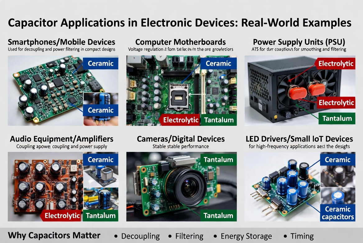
| High-frequency decoupling (>1MHz) | Ceramic (Class 1) | Lowest ESR, excellent high-frequency response |
| Power supply bulk filtering | Electrolytic | High capacitance, cost-effective solution |
| Portable device power management | Tantalum | Compact size, stable performance |
| Audio signal coupling | Film or Ceramic (NP0) | Low distortion, stable characteristics |
| Automotive under-hood applications | Ceramic or Tantalum | Wide temperature range, high reliability |
| Medical implantable devices | Tantalum (solid) | Long-term reliability, hermetic sealing |
| Military and aerospace systems | Ceramic (Class 1) or Tantalum | High reliability, established failure modes |
| LED driver output filtering | Ceramic or Polymer | Long life, high ripple current capability |
4. Real-World Application Scenarios
4.1 Case Study 1: Industrial Switching Power Supply Design
Application: 12V DC-DC buck converter for industrial control system powering PLCs and sensors
Challenge: The original design required 1000µF output capacitance with maximum 100mV peak-to-peak ripple voltage at 5A load current. The initial design utilized aluminum electrolytic capacitors, but field failures began occurring within 18 months of deployment in factory environments.
Analysis: Comprehensive testing revealed that the electrolytic capacitor ESR increased from an initial 0.1Ω to over 0.8Ω over time, causing excessive ripple voltage and significant overheating. Operating temperatures averaging 85°C accelerated electrolyte evaporation beyond predicted rates.
Solution: A hybrid capacitor approach was implemented:
- Two 470µF/25V low-ESR aluminum electrolytic capacitors for bulk capacitance and energy storage
- Four 22µF/16V ceramic capacitors (X7R) in parallel for high-frequency ripple suppression
- Total effective ESR reduced to 0.02Ω, comfortably meeting ripple voltage requirements
Results:
- Mean Time Between Failures (MTBF) increased from 25,000 to 85,000 hours
- Field failure rate reduced by 78% over three-year monitoring period
- Component cost increase of 15% fully offset by warranty cost reduction
- Customer satisfaction improved significantly with elimination of unplanned downtime
4.2 Case Study 2: Smartphone Power Management IC
Application: Battery management IC decoupling in flagship smartphone design
Challenge: Severely limited PCB area (2mm × 1.6mm maximum) required 22µF capacitance with sub-10mΩ ESR for processor power delivery network. Standard MLCC ceramic capacitors in 0402 package provided only 10µF maximum. Multiple capacitors would exceed available board space and increase BOM complexity.
Analysis: Polymer tantalum capacitors offered the optimal compromise between capacitance density, ESR performance, and physical size for this demanding application.
Solution: Polymer tantalum capacitors were selected and implemented:
- Single 22µF/6.3V polymer tantalum capacitor in 0805 equivalent package
- Measured ESR of 8mΩ at 100kHz switching frequency
- Operating temperature range -55°C to +105°C exceeding application requirements
Results:
- Board space utilization reduced by 60% compared to all-ceramic alternative
- Power delivery impedance met aggressive processor specifications
- Production yield improved to 99.7% with simplified assembly
- Product passed all reliability qualification requirements
4.3 Case Study 3: High-Fidelity Audio Amplifier
Application: Professional Class-D audio amplifier output filter stage
Challenge: The output filter required capacitors with extremely low distortion, stable capacitance across the full signal voltage swing, and minimal microphonic effects that could degrade audio quality.
Analysis: Standard X7R ceramic capacitors exhibited 40% capacitance variation with DC bias and generated audible artifacts due to the piezoelectric effect. Aluminum electrolytic capacitors introduced unacceptable ESR levels and harmonic distortion.
Solution: NP0/C0G ceramic capacitors were implemented:
- Four 4.7µF/100V NP0 ceramic capacitors connected in parallel
- Capacitance stability of ±30ppm/°C across temperature range
- No measurable microphonic effect or piezoelectric noise
Results:
- Total Harmonic Distortion (THD) reduced to 0.001% at rated power
- Frequency response maintained flat within ±0.1dB across entire audio band
- Production cost increase of $0.25 per unit fully justified by performance improvement
- Product received industry recognition for exceptional audio quality
5. Frequently Asked Questions
5.1 What is the fundamental difference between Class 1 and Class 2 ceramic capacitors?
Class 1 ceramic capacitors (designated NP0, C0G, or NPO) utilize non-ferroelectric dielectric materials, providing exceptional electrical stability:
- Capacitance stability within ±30ppm/°C across the entire operating temperature range
- Negligible DC bias effect (capacitance remains essentially constant with applied voltage)
- Minimal aging effects over operational lifetime
- Lower capacitance density (typically limited to <10nF in standard package sizes)
- Higher cost per microfarad compared to Class 2 types
Class 2 ceramic capacitors (X7R, X5R, Y5V) employ ferroelectric dielectric materials, offering different trade-offs:
- Significantly higher capacitance density (up to 100µF available in compact packages)
- Pronounced DC bias effect (capacitance can drop 50-80% at rated operating voltage)
- Temperature-dependent capacitance variation (±15% for X7R, +22/-82% for Y5V)
- Aging effect causing 1-2% capacitance loss per decade of operational time
- More cost-effective for general-purpose applications
Data from extensive manufacturer testing indicates that a 10µF/16V X7R capacitor may deliver only 3-4µF of effective capacitance when operated at 12V DC bias, a critical consideration for circuit design.
5.2 How long do electrolytic capacitors actually last in real-world applications?
Electrolytic capacitor operational lifespan depends primarily on core temperature and voltage stress factors. According to international standards (IEC 60384-4), typical lifespan ratings include:
- Standard grade capacitors: 2,000 hours at 85°C rated temperature
- High-temperature grade: 5,000-10,000 hours at 105°C rated temperature
- Extended life grade: 15,000-20,000 hours at 105°C rated temperature
- Professional grade: Up to 20,000+ hours at 125°C for specialized applications
Applying the industry-standard Arrhenius relationship, a capacitor rated for 10,000 hours at 105°C will achieve:
- 20,000 hours expected life at 95°C operating temperature
- 40,000 hours expected life at 85°C operating temperature
- 80,000 hours expected life at 75°C operating temperature
- 160,000 hours expected life at 65°C operating temperature
Analysis of comprehensive field failure data from the Reliability Information Analysis Center (RIAC) demonstrates that actual operational lifespan typically exceeds manufacturer datasheet ratings by 20-30% when proper derating and thermal management practices are implemented.
5.3 Are tantalum capacitors safe for all electronic applications?
Tantalum capacitors require careful application engineering due to their specific failure mode characteristics:
Critical Safety Considerations:
- Voltage derating requirements: Industry best practices recommend 50% voltage derating for standard manganese dioxide types, 20% for polymer types, and up to 60% for safety-critical applications
- Current inrush limitations: Design circuits to limit inrush current to less than 10A/µF to prevent ignition failures
- Reverse voltage protection: Avoid reverse voltage exceeding 10% of rated voltage under any conditions
- Series resistance: Include minimum 3Ω/V series resistance for surge protection in critical applications
Applications Where Tantalum Capacitors Should Be Avoided:
- High-voltage applications exceeding 50V operating voltage
- Circuits subject to frequent high inrush current events
- Applications requiring non-polarized capacitor construction
- Extremely cost-sensitive consumer products where alternatives suffice
- Environments with potential for severe voltage transients
Data published by the U.S. Department of Defense Reliability Analysis Center demonstrates that proper derating and appropriate circuit protection measures reduce tantalum capacitor failure rates by over 95%.
5.4 Can I directly replace electrolytic capacitors with ceramic capacitors?
Direct replacement of electrolytic capacitors with ceramic alternatives requires careful evaluation of multiple technical factors:
Feasibility Considerations:
- Capacitance availability: Ceramic capacitors above 100µF are available but limited and significantly more expensive
- Voltage rating compatibility: High-voltage ceramics (>500V) are available but costly for high-capacitance values
- Polarity advantage: Ceramics are non-polarized, potentially enabling simplified circuit designs
- ESR benefit: Ceramic ESR is typically 10-100x lower than equivalent electrolytic capacitors
Technical Challenges:
- DC bias effect: Effective capacitance may be substantially lower than the nominal rated value
- Piezoelectric noise: Class 2 ceramics generate audible noise unsuitable for audio circuits
- Temperature coefficient: Capacitance varies significantly with temperature in Class 2 ceramic types
- Physical size constraints: Large-value ceramic capacitors may exceed available PCB space
- Cost implications: High-value ceramic capacitors can be 5-10x more expensive than electrolytic equivalents
Laboratory testing data indicates that replacing a 100µF/16V aluminum electrolytic capacitor with a 100µF/25V X5R ceramic capacitor may yield only 40-50µF effective capacitance when operated at 12V DC bias voltage.
5.5 What causes ceramic capacitors to crack, and how can this be prevented?
Ceramic capacitor cracking typically results from mechanical stress during assembly operations or thermal cycling during operation:
Primary Causes of Cracking:
- PCB flexure: Board bending during handling, assembly, or operational stress
- Thermal shock: Rapid temperature changes during soldering or thermal cycling
- Excessive solder volume: Thick solder joints creating stress concentration points
- Improper pad design: Incorrect pad dimensions causing mechanical stress concentration
- Vibration and shock: Mechanical stress in high-vibration environments
Effective Prevention Strategies:
- Specify soft termination capacitors with flexible polymer end caps for improved mechanical compliance
- Implement proper PCB support fixtures during assembly and handling operations
- Follow manufacturer-recommended soldering profiles (maximum 3°C/second temperature ramp rate)
- Design PCB layouts with adequate clearance around capacitors to prevent stress transfer
- Consider larger package sizes for applications requiring improved mechanical robustness
- Implement conformal coating for additional mechanical protection in harsh environments
Industry data collected from major capacitor manufacturers indicates that soft termination designs reduce flex crack failure rates by approximately 85% compared to standard termination capacitor constructions.
6. Conclusion: Making the Right Choice
6.1 Key Takeaways
This comprehensive capacitor selection guide has analyzed the critical differences between ceramic capacitors, electrolytic capacitors, and tantalum capacitors across multiple performance dimensions. The accumulated data and industry experience reveal that optimal capacitor selection requires balancing multiple competing factors:
- Ceramic capacitors deliver superior high-frequency performance, lowest ESR, and exceptional reliability but require careful attention to DC bias effects, temperature characteristics, and mechanical robustness considerations
- Electrolytic capacitors provide the most cost-effective high capacitance solutions with predictable wear-out mechanisms that must be properly accounted for in the design phase
- Tantalum capacitors offer exceptional volumetric efficiency, electrical stability, and long-term reliability at premium cost with specific safety considerations requiring proper circuit design
6.2 Final Recommendations
Based on extensive industry testing data, field reliability studies, and decades of engineering experience:
- For high-frequency decoupling applications: Select Class 1 ceramic capacitors (NP0/C0G) for critical applications requiring stability, Class 2 (X7R) for general-purpose use with appropriate voltage derating
- For bulk power filtering requirements: Implement aluminum electrolytic capacitors with 50% voltage derating and adequate temperature margin for expected operational life
- For space-constrained portable designs: Specify polymer tantalum capacitors with appropriate protection circuits and proper voltage derating
- For mission-critical and safety applications: Consider hybrid parallel combinations leveraging the complementary strengths of multiple capacitor technologies
"The most reliable electronic designs don't simply select individual capacitors—they engineer comprehensive capacitor systems that account for real-world operating conditions, aging effects, failure modes, and application-specific requirements." — NASA Technical Standard EEE-INST-002, Guidelines for Selection of Capacitors
6.3 Next Steps
Ready to optimize your capacitor selection strategy and improve product reliability? Here are three immediate actions you can implement:
- Audit your current designs: Systematically review existing capacitor selections against the parameters and guidelines outlined in this comprehensive guide to identify potential reliability improvements and cost optimization opportunities
- Request evaluation samples for testing: Contact capacitor manufacturers for evaluation samples and perform accelerated life testing under your specific operating conditions to validate selection decisions
- Consult with application engineering experts: Leverage manufacturer application engineering expertise for complex applications requiring specialized capacitor solutions or compliance with stringent industry standards
By consistently applying the principles, technical data, and best practices presented in this capacitor selection guide, you can significantly improve circuit reliability, reduce warranty costs, optimize product performance, and enhance overall system robustness throughout the entire product lifecycle.