


Crystal Oscillator vs PLL Synthesizer: Performance, Tradeoffs, and Applications
When designing electronic systems that require precise timing signals, engineers face a critical decision: should they use a crystal oscillator or a PLL (Phase-Locked Loop) clock synthesizer? This choice significantly impacts system performance, cost, power consumption, and design flexibility. In high-speed digital designs, communication systems, and embedded applications, the wrong selection can lead to timing violations, signal integrity issues, or unnecessary complexity. This guide provides a technical comparison of crystal oscillators and PLL synthesizers, helping design engineers, R&D teams, and hardware architects make informed component selection decisions based on their specific application requirements.
Table of Contents
- Key Technical Parameters Explained
- Crystal Oscillator Architecture and Performance
- PLL Synthesizer Architecture and Performance
- Performance Comparison: Phase Noise, Jitter, and Stability
- Application-Specific Selection Guidelines
- Design Considerations and Common Pitfalls
- FAQ
- Conclusion
1. Key Technical Parameters Explained
Before comparing crystal oscillators and PLL synthesizers, it's essential to understand the critical performance metrics that drive component selection decisions.
Phase Noise represents the frequency domain view of timing jitter and directly impacts signal quality. Measured in dBc/Hz at specific offset frequencies from the carrier, phase noise determines how much the actual signal deviates from an ideal sinusoid. In RF applications, phase noise translates directly to adjacent channel interference and receiver sensitivity degradation. Close-in phase noise (measured at offsets from 1 Hz to 1 kHz) is particularly critical for narrow-band communication systems, while far-out phase noise affects broadband applications.
Jitter is the time domain equivalent of phase noise, representing cycle-to-cycle variations in signal timing. Period jitter measures the deviation of each clock period from the ideal period, while cycle-to-cycle jitter quantifies variations between consecutive cycles. For high-speed digital interfaces like PCIe, USB, or SATA, jitter specifications are typically defined in picoseconds and directly determine the maximum achievable data rate and bit error rate performance.
Frequency Stability describes how well a clock source maintains its target frequency under varying environmental conditions. This includes initial accuracy at manufacturing, temperature coefficient (measured in ppm/°C), aging rate (measured in ppm/year), and load pulling effects. Crystal-based sources typically achieve stability of ±10 to ±50 ppm over temperature, while voltage-controlled oscillators in PLL synthesizers may have significantly higher drift without compensation.
Settling Time and Lock Time matter significantly in systems requiring frequency changes. Crystal oscillators reach stable operation within microseconds of power-up, while PLL synthesizers require lock time ranging from microseconds to milliseconds depending on loop bandwidth and frequency step size. This becomes critical in frequency-hopping spread spectrum systems or power-managed designs with frequent sleep/wake cycles.
Power Consumption varies dramatically between the two technologies. Simple crystal oscillators consume 1-10 mW in typical applications, while PLL synthesizers with integrated VCOs and dividers typically consume 20-200 mW depending on output frequency and the number of outputs. For battery-powered IoT devices or portable medical instruments, this difference can significantly impact battery life.
2. Crystal Oscillator Architecture and Performance
Crystal oscillators leverage the piezoelectric effect in quartz crystals to generate highly stable frequency references. When voltage is applied across a properly cut quartz crystal, it mechanically resonates at a precise frequency determined by its physical dimensions and crystal cut angle.
The basic crystal oscillator circuit consists of the quartz crystal resonator, a sustaining amplifier, and frequency-determining components. The crystal acts as a high-Q resonator (quality factors typically ranging from 10,000 to 100,000), providing exceptional frequency selectivity. Common oscillator topologies include Pierce, Colpitts, and Butler configurations, each offering different tradeoffs between startup reliability, output signal quality, and drive level sensitivity.
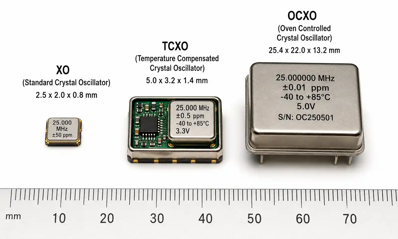
Temperature Compensated Crystal Oscillators (TCXO) add compensation circuitry to counteract the crystal's natural frequency drift over temperature. By measuring temperature and applying correction voltage to a varactor, TCXOs achieve stability of ±0.5 to ±2 ppm over the full operating temperature range. This makes them suitable for GPS receivers, cellular base stations, and precision instrumentation where frequency accuracy directly impacts system performance.
Oven Controlled Crystal Oscillators (OCXO) take stability further by maintaining the crystal at a constant elevated temperature inside a miniature oven. OCXOs achieve stability of ±0.001 to ±0.1 ppm, providing the best phase noise and aging characteristics available in a compact form factor. The tradeoff is significantly higher power consumption (1-5 watts) and longer warm-up time (1-5 minutes), making OCXOs suitable only for stationary equipment with stable power supplies.
The primary limitation of crystal oscillators is frequency inflexibility. Each crystal is cut and manufactured for a specific fundamental frequency, typically ranging from 1 MHz to 200 MHz. Higher frequencies require overtone operation or external frequency multiplication, which can degrade phase noise performance. Designers needing multiple clock frequencies must either use multiple crystals or add frequency dividers and multipliers.
| Crystal Oscillator Type | Frequency Stability | Phase Noise (10 kHz offset) | Power Consumption | Typical Cost | Startup Time |
|---|---|---|---|---|---|
| Standard XO | ±50 ppm | -140 dBc/Hz | 1-5 mW | $0.50-$2 | 2-5 ms |
| TCXO | ±0.5 ppm | -145 dBc/Hz | 5-20 mW | $2-$10 | 5-10 ms |
| OCXO | ±0.01 ppm | -155 dBc/Hz | 1-5 W | $20-$200 | 1-5 min |
| VCXO (Voltage Controlled) | ±25 ppm | -142 dBc/Hz | 3-10 mW | $1-$5 | 2-5 ms |
This table illustrates the fundamental tradeoff in crystal oscillator selection: improved stability and phase noise performance come at the cost of higher power consumption and cost. Standard crystal oscillators suffice for general-purpose microcontroller timing, while precision RF and test equipment applications justify OCXO performance and cost.
3. PLL Synthesizer Architecture and Performance
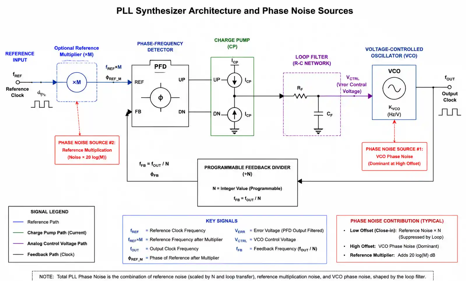
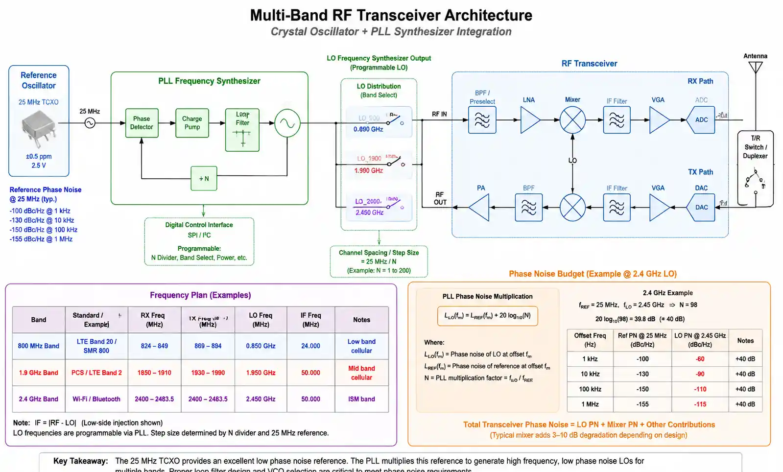
PLL clock synthesizers generate programmable output frequencies by phase-locking a voltage-controlled oscillator (VCO) to a stable reference frequency, typically provided by a crystal oscillator. This architecture enables a single reference crystal to generate multiple output frequencies with high precision.
The core PLL consists of a phase-frequency detector (PFD), charge pump, loop filter, VCO, and feedback divider. The PFD compares the reference frequency with the divided VCO output, generating error signals that adjust the VCO frequency until phase lock is achieved. The loop filter bandwidth determines tradeoff between lock time and phase noise performance—wider bandwidth provides faster locking but allows more VCO noise to appear at the output.
Integer-N PLLs divide the VCO frequency by an integer value, limiting output frequencies to multiples of the reference frequency. For example, with a 10 MHz reference, an integer-N PLL can only generate 20 MHz, 30 MHz, 40 MHz, and so on. This simplicity results in relatively low in-band phase noise, making integer-N synthesizers suitable for applications where discrete frequency steps are acceptable.
Fractional-N PLLs use sophisticated divider control and delta-sigma modulation to achieve fractional division ratios, enabling much finer frequency resolution. A fractional-N PLL with a 10 MHz reference can generate any frequency with resolution down to a few hertz. The challenge is that fractional operation introduces quantization noise and fractional spurs, requiring careful loop filter design and sometimes additional calibration to achieve acceptable spurious performance.
Modern integrated PLL synthesizers often include multiple outputs with independent dividers, enabling a single device to generate all clocks needed in a complex system. For example, a typical high-integration clock generator might provide a 156.25 MHz Ethernet clock, a 100 MHz processor clock, a 48 MHz USB clock, and a 32.768 kHz RTC clock—all derived from a single 25 MHz crystal reference.
Performance Challenges in PLL synthesizers stem primarily from the VCO. LC-based VCOs achieve the best phase noise but have limited tuning range (typically 20-50%). Ring oscillator VCOs cover wider frequency ranges but exhibit significantly worse phase noise. The VCO's phase noise is multiplied by the division ratio (in units of dB), so generating high output frequencies from low reference frequencies amplifies the VCO noise contribution.
| PLL Synthesizer Type | Frequency Range | Phase Noise (10 kHz offset) | Lock Time | Power Consumption | Frequency Resolution |
|---|---|---|---|---|---|
| Integer-N PLL | 10 MHz - 2 GHz | -110 dBc/Hz | 10-100 µs | 50-150 mW | Reference freq. |
| Fractional-N PLL | 1 MHz - 6 GHz | -105 dBc/Hz | 50-500 µs | 80-200 mW | < 1 Hz |
| Multi-output Clock Generator | 1 kHz - 800 MHz | -115 dBc/Hz | 100-1000 µs | 100-300 mW | Reference / divider |
| Jitter Cleaner PLL | 1 MHz - 1 GHz | -130 dBc/Hz | 1-10 ms | 200-500 mW | Tracks input |
This comparison shows that PLL synthesizers trade phase noise performance for frequency flexibility. Jitter cleaner PLLs represent a special category designed specifically to filter input jitter and regenerate clean clocks, bridging the gap between PLL convenience and crystal oscillator performance.
4. Performance Comparison: Phase Noise, Jitter, and Stability
Understanding the detailed performance differences between crystal oscillators and PLL synthesizers is crucial for making appropriate design decisions.
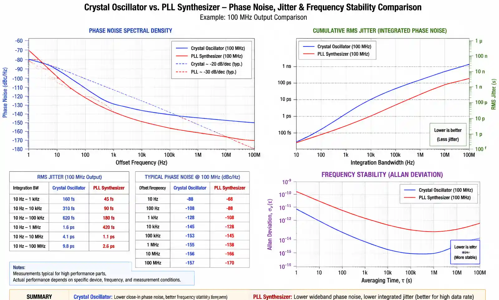
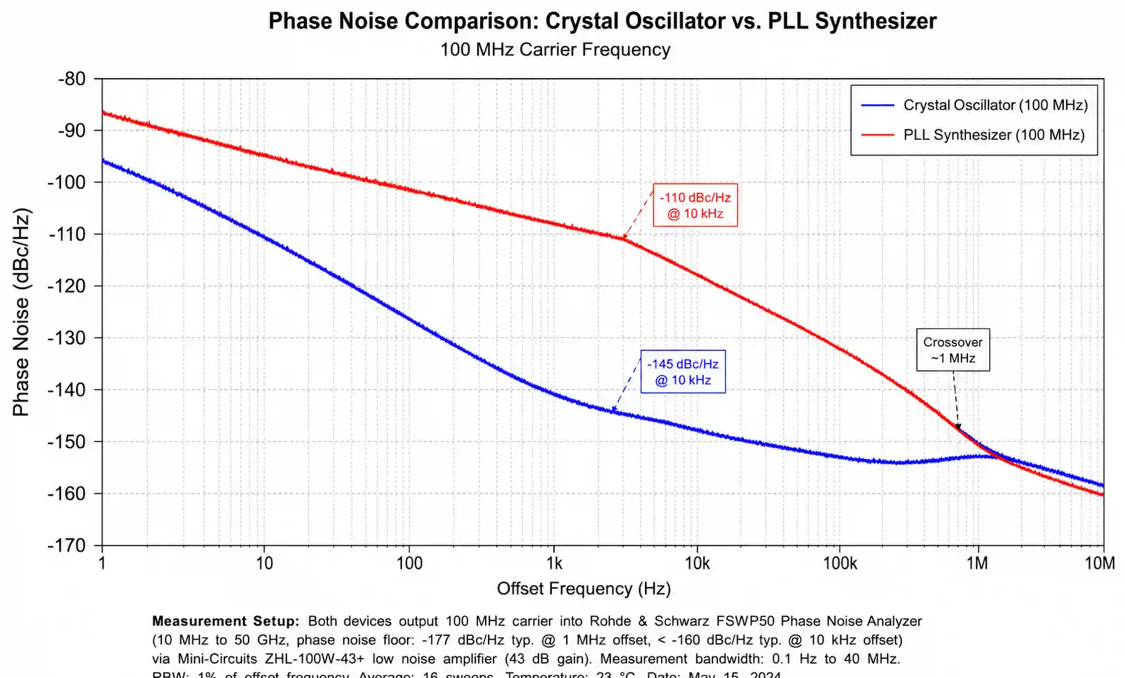
Phase Noise Comparison reveals the fundamental advantage of crystal oscillators. A typical 100 MHz crystal oscillator achieves phase noise of -145 dBc/Hz at 10 kHz offset, -160 dBc/Hz at 100 kHz offset, and -165 dBc/Hz at 1 MHz offset. In contrast, a PLL synthesizer generating 100 MHz from a 25 MHz reference typically shows -110 dBc/Hz at 10 kHz offset, improving to -140 dBc/Hz at 100 kHz offset and -145 dBc/Hz at 1 MHz offset.
The phase noise profile difference stems from the PLL's two-regime behavior. At offset frequencies inside the loop bandwidth (typically 10 kHz to 1 MHz), the output phase noise is dominated by the reference source multiplied by 20×log(N), where N is the division ratio. Outside the loop bandwidth, the VCO's free-running phase noise dominates. Crystal oscillators, having no frequency multiplication, exhibit a smooth phase noise profile dictated purely by the resonator Q and sustaining amplifier noise.
Jitter Performance follows directly from integrated phase noise. For a 100 MHz clock, a crystal oscillator typically achieves 200-500 femtoseconds RMS jitter integrated from 12 kHz to 20 MHz, while a PLL synthesizer produces 1-5 picoseconds RMS jitter for the same integration bandwidth. This 5-10× jitter difference directly impacts maximum data rates in high-speed serial interfaces.
Frequency Stability Over Temperature heavily favors crystal oscillators for applications requiring absolute frequency accuracy. An uncompensated crystal oscillator exhibits ±25 to ±50 ppm stability from -40°C to +85°C, while a PLL synthesizer's stability is determined by its reference crystal plus additional temperature-dependent drift from the VCO, charge pump, and dividers. Without temperature compensation, PLL synthesizers can drift ±50 to ±200 ppm over temperature.
Long-term Aging also differs significantly. Crystal oscillators age at rates of 1-5 ppm per year due to gradual changes in the quartz crystal structure and mounting stress. PLL synthesizers inherit the crystal reference aging plus additional drift from component aging in the loop filter and VCO. Over a 10-year product lifetime, this can accumulate to 10-50 ppm frequency shift requiring periodic recalibration in precision applications.
| Performance Metric | Crystal Oscillator (100 MHz) | PLL Synthesizer (100 MHz from 25 MHz ref) | Impact on Application |
|---|---|---|---|
| Phase Noise @ 10 kHz offset | -145 dBc/Hz | -110 dBc/Hz | RF receiver sensitivity, ADC SNR |
| Phase Noise @ 1 MHz offset | -165 dBc/Hz | -145 dBc/Hz | Broadband communication, sampling jitter |
| RMS Jitter (12 kHz - 20 MHz) | 300 fs | 2 ps | SerDes eye opening, data rate limits |
| Temperature Stability | ±25 ppm | ±50 ppm (w/ TCXO ref) | Frequency accuracy, channel spacing |
| Startup Time | 2-5 ms | 100-1000 µs | Power management, frequency hopping |
| Frequency Agility | Fixed (no tuning) | Full range in µs-ms | Multi-band operation, test equipment |
This detailed comparison reveals that the choice between crystal oscillators and PLL synthesizers is rarely clear-cut. Instead, it depends heavily on which specifications are most critical for the target application and whether the performance compromises of PLL synthesis are acceptable for the gained frequency flexibility.
5. Application-Specific Selection Guidelines
Selecting between crystal oscillators and PLL synthesizers requires careful analysis of application-specific requirements. The following guidelines help narrow the decision based on system architecture and performance needs.
High-Speed Digital Interfaces (PCIe, USB, SATA, Ethernet) have stringent jitter requirements explicitly specified in their standards. PCIe Gen3 requires less than 1 ps RMS jitter (12 kHz - 20 MHz integration), while USB 3.0 specifies 150 ps peak-to-peak jitter. These specifications typically demand crystal oscillators or specialized low-jitter PLL clock generators with jitter cleaning capability. Standard PLL synthesizers often fail to meet these requirements without additional jitter attenuation circuits.
RF Communication Systems present a nuanced tradeoff. The local oscillator in a radio receiver or transmitter must have excellent close-in phase noise to prevent reciprocal mixing and adjacent channel interference. In single-frequency designs like ISM band radios operating at fixed 2.4 GHz, a crystal oscillator with frequency multiplication provides the best phase noise performance. However, multi-band cellular radios, software-defined radios, and frequency-hopping systems require frequency agility that only PLL synthesizers can provide, accepting the phase noise compromise.
Embedded Systems and Microcontrollers typically use crystal oscillators as primary clock sources due to their simplicity, low cost, and low power consumption. A 16 MHz crystal driving an ARM Cortex-M4 microcontroller consumes less than 2 mW and provides more than adequate stability for most embedded applications. Internal PLL synthesizers within the microcontroller then generate higher CPU frequencies and peripheral clocks as needed, keeping external component count and cost minimal.
Test and Measurement Equipment demands the absolute best frequency accuracy and stability, making OCXO crystal oscillators the standard choice. Oscilloscopes, spectrum analyzers, network analyzers, and arbitrary waveform generators all rely on 10 MHz OCXO references to achieve parts-per-billion frequency accuracy. High-end instruments often include GPS-disciplined OCXOs for long-term stability, while using PLL synthesizers only for generating multiple swept or programmable frequencies after the ultra-stable reference.
Automotive Applications must consider extreme temperature ranges (-40°C to +125°C), vibration, and EMI requirements. TCXO crystal oscillators provide the necessary stability for safety-critical systems like ADAS camera timing and radar reference clocks. CAN and LIN bus timing uses simple crystal oscillators. However, automotive Ethernet (100BASE-T1, 1000BASE-T1) and SerDes links for camera interfaces increasingly require low-jitter PLL clock generators due to multiple frequency requirements and tight jitter specifications.
| Application Domain | Preferred Solution | Key Selection Drivers | Typical Frequency Accuracy | Typical Phase Noise Requirement |
|---|---|---|---|---|
| PCIe / USB / SATA | Low-jitter XO or Jitter Cleaner PLL | Jitter specs, standards compliance | ±50 ppm | < 1 ps RMS jitter |
| Cellular Base Station | OCXO + PLL Synthesizer | Frequency stability, multi-band | ±0.1 ppm | -130 dBc/Hz @ 10 kHz |
| IoT Wireless Sensor | Standard XO | Cost, power consumption | ±50 ppm | -120 dBc/Hz @ 10 kHz |
| Precision Instrumentation | OCXO | Long-term stability, accuracy | ±0.01 ppm | -150 dBc/Hz @ 10 kHz |
| Automotive SerDes | TCXO + Low-jitter PLL | Temperature stability, multi-output | ±5 ppm | < 2 ps RMS jitter |
| GPS Receiver | TCXO | Holdover accuracy, temperature stability | ±0.5 ppm | -135 dBc/Hz @ 10 kHz |
When evaluating specific components for these applications, always verify performance against the actual system requirements rather than assuming typical values. Request evaluation boards and measure phase noise and jitter in your specific PCB layout and power supply environment, as implementation details significantly affect real-world performance.
6. Design Considerations and Common Pitfalls
Successful implementation of either crystal oscillators or PLL synthesizers requires attention to PCB layout, power supply design, and proper component selection. Common mistakes can degrade performance by 10-20 dB or cause intermittent failures.
Crystal Oscillator PCB Layout requires careful attention to the oscillator circuit and traces. Keep crystal connections as short as possible—trace lengths exceeding 20 mm add parasitic capacitance that shifts operating frequency and reduces startup margin. Place load capacitors immediately adjacent to the crystal with ground return paths going directly to the IC ground pin without traveling through noisy ground planes. Never route high-speed digital signals or switching power supply traces near crystal circuits.
A common mistake is incorrect load capacitance calculation. Most crystal datasheets specify load capacitance (typically 8 pF, 12 pF, or 18 pF), but the required external capacitor value must account for PCB trace capacitance (typically 2-5 pF) and IC pin capacitance (specified in the microcontroller datasheet). The correct external capacitor value is C_ext = 2×(C_load - C_stray - C_pin). Using incorrect values can prevent oscillation startup or shift the frequency beyond acceptable limits.
PLL Synthesizer Loop Filter Design critically determines phase noise, spurious performance, and lock time. The loop filter must be designed for the specific PLL architecture, charge pump current, and VCO gain (K_VCO). Many engineers mistakenly use reference designs without adjustment for their specific operating frequency, resulting in suboptimal performance or instability. Use the manufacturer's design tools or spreadsheet calculators, then verify loop bandwidth and phase margin through simulation before prototype fabrication.
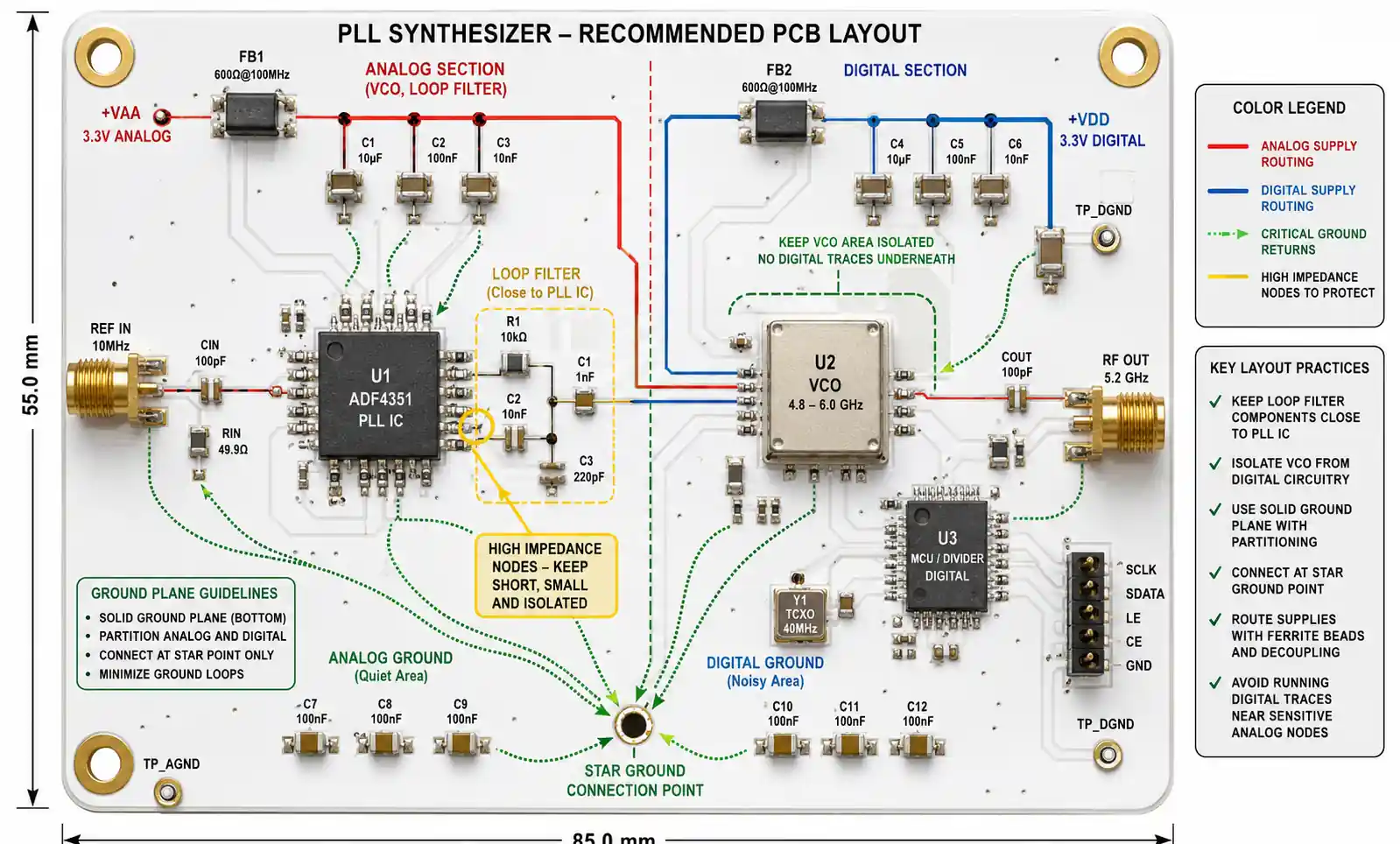
Power Supply Noise Coupling affects both crystal oscillators and PLL synthesizers but is particularly critical for PLLs. The VCO control voltage is highly sensitive to power supply noise—1 mV of ripple on the VCO supply can translate to significant spurious sidebands. Use dedicated low-noise LDO regulators for analog PLL supply pins, with local ferrite beads and bypass capacitors placed within 2 mm of the supply pin. Never share supply rails between PLL circuits and switching regulators, digital logic, or high-current loads.
Reference Clock Quality is crucial for PLL synthesizers but often overlooked. A PLL cannot improve reference clock quality—it can only add its own noise. Using a noisy crystal oscillator as a PLL reference results in poor output phase noise regardless of the PLL design. For applications requiring excellent phase noise, invest in a high-quality TCXO reference (phase noise better than -140 dBc/Hz at 10 kHz offset) rather than a standard crystal oscillator.
Thermal Management becomes critical for OCXO and high-power PLL synthesizers. An OCXO dissipating 2-5 watts in a compact enclosure will self-heat significantly. Ensure adequate thermal coupling to a heat spreader or chassis, and avoid placing temperature-sensitive components nearby. For PLL synthesizers, elevated junction temperature degrades VCO phase noise and increases divider jitter—keep junction temperature below 85°C through proper PCB thermal design.
Common Failure Modes to avoid include: crystal oscillators failing to start due to excessive drive level or insufficient negative resistance margin (verify with manufacturer specifications and measurement), PLL synthesizers failing to lock due to incorrect loop filter values or insufficient VCO tuning range, spurious outputs from PLL synthesizers due to reference spurs, fractional spurs, or power supply coupling, and intermittent frequency jumping in PLLs due to inadequate power supply decoupling or EMI coupling into the loop filter.
7. FAQ
What is the main difference between a crystal oscillator and a PLL synthesizer?
A crystal oscillator generates a fixed frequency determined by a physical quartz crystal resonator, offering excellent phase noise and stability. A PLL synthesizer uses a crystal reference to generate programmable output frequencies through phase-locked loop circuitry, providing frequency flexibility at the cost of somewhat degraded phase noise performance. Crystal oscillators are simpler and consume less power, while PLL synthesizers enable multiple frequencies from a single reference.
Can a PLL synthesizer achieve the same phase noise as a crystal oscillator?
Not in typical implementations. At close-in offset frequencies (10 kHz), crystal oscillators achieve -145 dBc/Hz while standard PLL synthesizers produce -110 dBc/Hz. However, specialized jitter cleaner PLLs with very narrow loop bandwidths can approach crystal oscillator performance by heavily filtering the VCO noise, achieving -130 to -135 dBc/Hz. The tradeoff is significantly longer lock times (milliseconds instead of microseconds).
How do I calculate the required load capacitors for a crystal oscillator?
Use the formula C_ext = 2×(C_load - C_stray - C_pin), where C_load is the specified load capacitance from the crystal datasheet (typically 8-18 pF), C_stray is PCB trace capacitance (typically 2-5 pF), and C_pin is the IC input capacitance from the microcontroller datasheet (typically 3-5 pF). For example, with an 18 pF load crystal, 3 pF stray capacitance, and 4 pF pin capacitance, you need C_ext = 2×(18 - 3 - 4) = 22 pF capacitors.
Which is better for battery-powered IoT devices?
Crystal oscillators typically consume 1-10 mW compared to 50-200 mW for PLL synthesizers, making them the clear choice for ultra-low-power applications. Most IoT wireless protocols (Bluetooth LE, Zigbee, LoRaWAN) operate at fixed frequencies where a single crystal oscillator suffices. Use the microcontroller's internal PLL if higher CPU frequencies are needed, keeping external components minimal. Only use external PLL synthesizers if multiple RF bands or complex clocking schemes are required.
What causes PLL synthesizers to have worse jitter than crystal oscillators?
PLL jitter comes from three sources: multiplication of reference phase noise by the division ratio (typically 10-20 dB degradation), VCO free-running phase noise outside the loop bandwidth, and charge pump/phase detector noise. Crystal oscillators avoid these issues by generating the target frequency directly without multiplication. Fractional-N PLLs add additional quantization noise from the delta-sigma modulator, further degrading jitter performance.
How do I choose between TCXO and OCXO for my application?
If your system can provide 1-5 watts of continuous power, can tolerate 1-5 minute warm-up time, and requires ±0.01 to ±0.1 ppm stability (precision instruments, base stations), use an OCXO. If your system is portable, requires fast startup, and can tolerate ±0.5 to ±2 ppm stability (GPS receivers, handheld radios, automotive), use a TCXO. Standard XOs suffice for applications with ±25 to ±50 ppm requirements (general microcontroller timing, consumer electronics).
Can I use a PLL synthesizer to clean up jitter from a noisy input clock?
Yes, but with careful design. Jitter cleaner PLLs specifically designed for this purpose use very narrow loop bandwidths (typically 100 Hz to 10 kHz) to heavily filter input jitter while maintaining frequency lock. Standard PLL synthesizers with wide loop bandwidths (100 kHz to 1 MHz) will pass through most input jitter. The tradeoff is that narrow loop bandwidths result in slow lock times and reduced ability to track input frequency changes.
What are the typical failure modes for crystal oscillators?
Common failures include: failure to start oscillation due to insufficient drive level or excessive load capacitance, frequency drift due to aging or mechanical stress on the crystal, intermittent operation due to vibration sensitivity, and gain margin loss at temperature extremes. Always verify startup margin under worst-case conditions (low voltage, high temperature) and ensure drive level stays within manufacturer specifications to avoid accelerated aging.
8. Conclusion
The choice between crystal oscillators and PLL synthesizers fundamentally depends on your application's priorities. Crystal oscillators deliver superior phase noise performance, lower power consumption, and simpler implementation, making them ideal for fixed-frequency applications where signal purity is paramount—high-speed serial interfaces, precision instrumentation, and ultra-low-power embedded systems. PLL synthesizers sacrifice some phase noise performance to enable frequency programmability, making them essential for multi-band RF systems, test equipment requiring swept frequencies, and complex digital systems needing multiple clock domains from a single reference.
For most embedded microcontroller applications, start with a crystal oscillator as the primary reference and leverage internal PLLs for CPU and peripheral clocking. For RF communication systems, evaluate whether your application requires frequency agility—if not, consider crystal oscillators with frequency multiplication for the best phase noise. If jitter is your primary concern (high-speed SerDes applications), invest in low-jitter crystal oscillators or specialized jitter cleaner PLLs rather than standard PLL synthesizers.
Before finalizing your selection, always verify phase noise and jitter performance in your actual system environment using measurement equipment or evaluation boards. Component datasheets show typical performance under ideal conditions—real-world performance depends heavily on PCB layout, power supply quality, and thermal design. When in doubt, request technical support from the manufacturer's field application engineers, who can help optimize your specific design for the best achievable performance.