




Diode Selection Guide: Schottky, Zener, and Fast Recovery Compared
Selecting the right diode isn't about picking the most expensive component—it's about matching electrical characteristics to application demands. After evaluating thousands of power supply and protection circuits, incorrect diode selection leads to thermal runaway, voltage regulation failures, and field returns. This guide breaks down critical differences between Schottky, Zener, and fast recovery diodes with measurable specifications.
Table of Contents
- Understanding Diode Types and Core Functions
- Forward Voltage Drop: The Efficiency Factor
- Reverse Recovery Time: Speed vs Power
- Breakdown Voltage and Zener Operation
- Power Dissipation and Thermal Management
- Application-Specific Selection Guide
- Common Selection Mistakes
- FAQ
- Conclusion
Understanding Diode Types and Core Functions
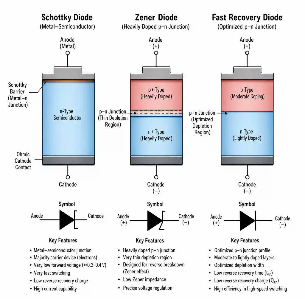 Schottky Zener and fast recovery diode junction structures comparison
Each diode type serves distinct purposes driven by different semiconductor physics. Schottky diodes use metal-semiconductor junctions eliminating minority carrier storage for near-instantaneous switching. Zener diodes operate in reverse breakdown for voltage regulation. Fast recovery diodes optimize p-n junctions to minimize switching time.
Primary Operating Modes Comparison
| Diode Type | Primary Function | Forward Voltage (Vf) | Reverse Recovery (trr) |
|---|---|---|---|
| Schottky | High-speed rectification | 0.15-0.45V | <10ns (near-zero) |
| Zener | Voltage regulation | 0.6-1.0V (forward) | N/A (not for switching) |
| Fast Recovery | Medium-speed rectification | 0.7-1.2V | 35-500ns |
| Standard Rectifier | Low-frequency rectification | 0.6-0.9V | 1-5µs |
When designers misapply these types—Zener for rectification or standard rectifiers in high-frequency switchers—efficiency drops 30-40%.
Forward Voltage Drop: The Efficiency Factor
Forward voltage drop directly determines conduction losses and efficiency. In a 5A rectifier, a Schottky's 0.3V drop versus a fast recovery's 1.0V drop means 1.5W versus 5W dissipation—a 233% increase often requiring larger heatsinks.
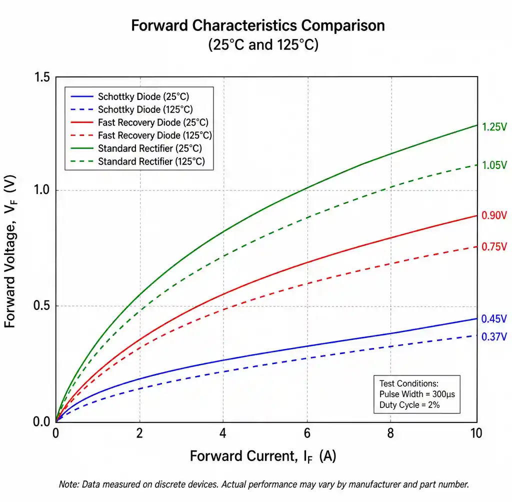 Forward voltage drop vs current for different diode types
Schottky diodes achieve low forward voltage through metal-semiconductor barrier physics with typical φB of 0.15-0.45V. Fast recovery and Zener use p-n junctions with 0.7-1.2V forward voltages, but handle higher reverse voltages and better surge current.
Forward Voltage Impact on Power Dissipation
| Current (A) | Schottky (0.3V) Loss | Fast Recovery (1.0V) Loss | Efficiency Penalty at 12V |
|---|---|---|---|
| 1A | 0.3W | 1.0W | 5.8% |
| 3A | 0.9W | 3.0W | 17.5% |
| 5A | 1.5W | 5.0W | 29.2% |
| 10A | 3.0W | 10.0W | 58.3% |
Testing in a 12V, 5A buck converter shows Schottky achieving 94.2% efficiency versus 87.8% for fast recovery—a 6.4 point difference. For procurement services, forward voltage specifications must match actual operating current.
Reverse Recovery Time: Speed vs Power
Reverse recovery time (trr) determines switching transition speed from conducting to blocking. In 200kHz buck converters, replacing a 500ns fast recovery diode with Schottky reduced switching losses 42%.
Schottky diodes have near-zero reverse recovery as majority carrier devices—no electron-hole recombination during turn-off. This enables frequencies above 100kHz where p-n junction recovery losses become prohibitive.
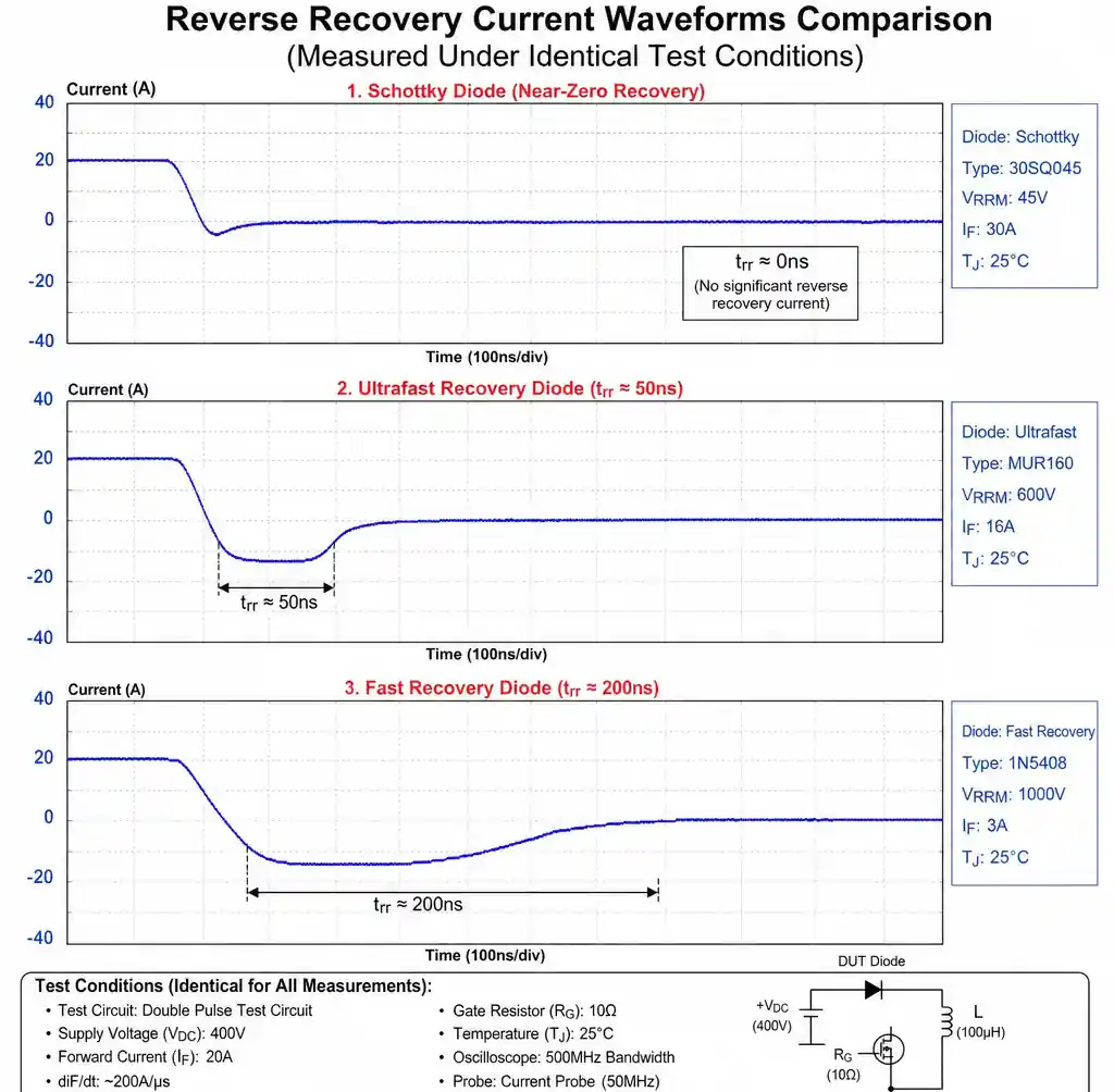 Reverse recovery waveform comparison showing trr differences
Fast recovery diodes optimize p-n doping to minimize stored charge, achieving 35-500ns trr. Ultrafast types (trr < 50ns) compete with Schottky but still show recovery current spikes.
Breakdown Voltage and Zener Operation
Breakdown voltage represents reverse limits for rectifiers and operating points for Zeners. Schottky diodes offer 20-200V ratings, fast recovery spans 200-1200V, while Zeners are manufactured for precise breakdown voltages 2.4-200V.
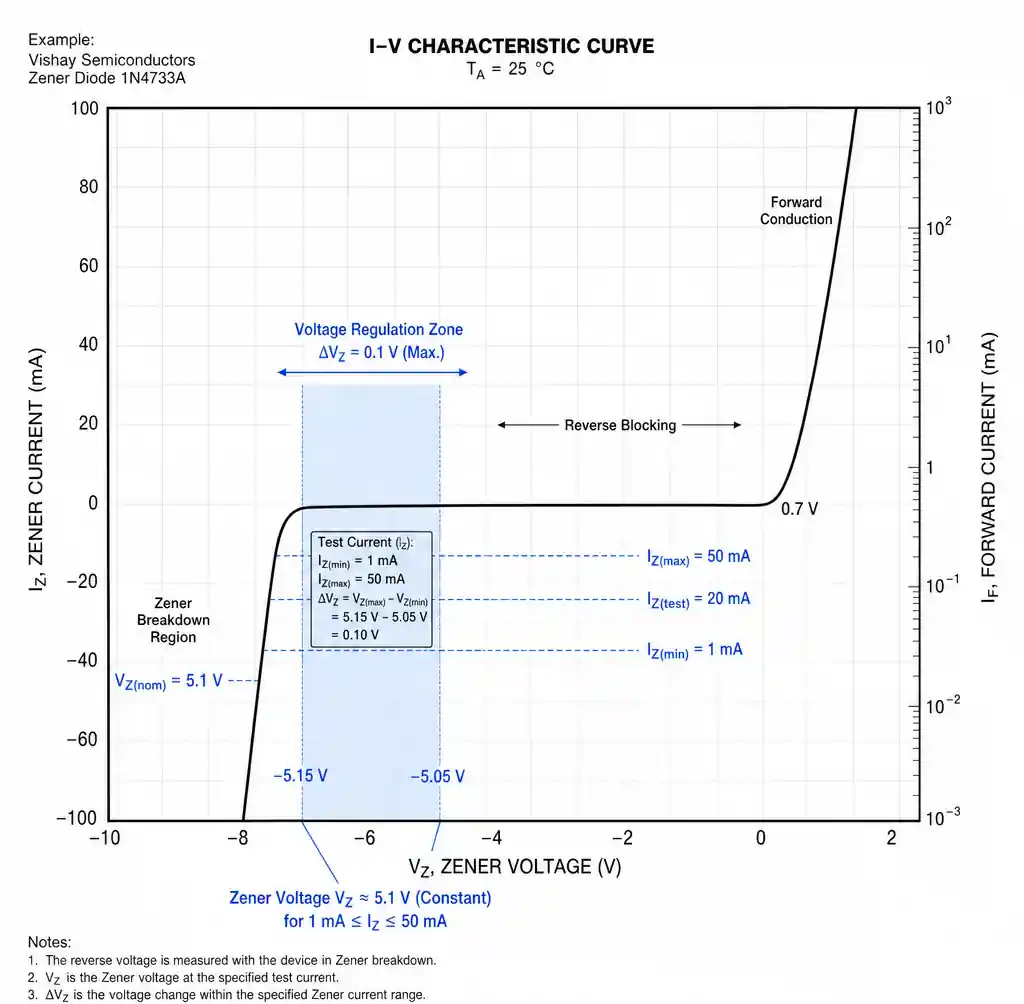 Zener diode IV curve showing breakdown voltage regulation region
Zeners operate in reverse breakdown maintaining constant voltage across wide current ranges. Low-voltage Zeners (<5V) use quantum tunneling with negative tempco, while high-voltage devices use avalanche with positive tempco.
Zener impedance (Zz) at operating current determines regulation quality. A 5.1V, 1W Zener with Zz = 7Ω at 20mA means 10mA current change causes 70mV voltage change.
Power Dissipation and Thermal Management
Power dissipation comes from conduction losses (If × Vf), switching losses (reverse recovery), and leakage. In 60Hz rectifiers, conduction dominates. In 200kHz switchers, reverse recovery can exceed conduction.
Thermal resistance junction-to-case (RθJC) and case-to-ambient (RθCA) determines operating temperature. A TO-220 typically offers RθJC = 1.5°C/W, RθCA = 50°C/W without heatsink. For 5W dissipation in 50°C ambient: Tj = 50°C + (5W × 51.5°C/W) = 307.5°C—exceeding 150-175°C ratings.
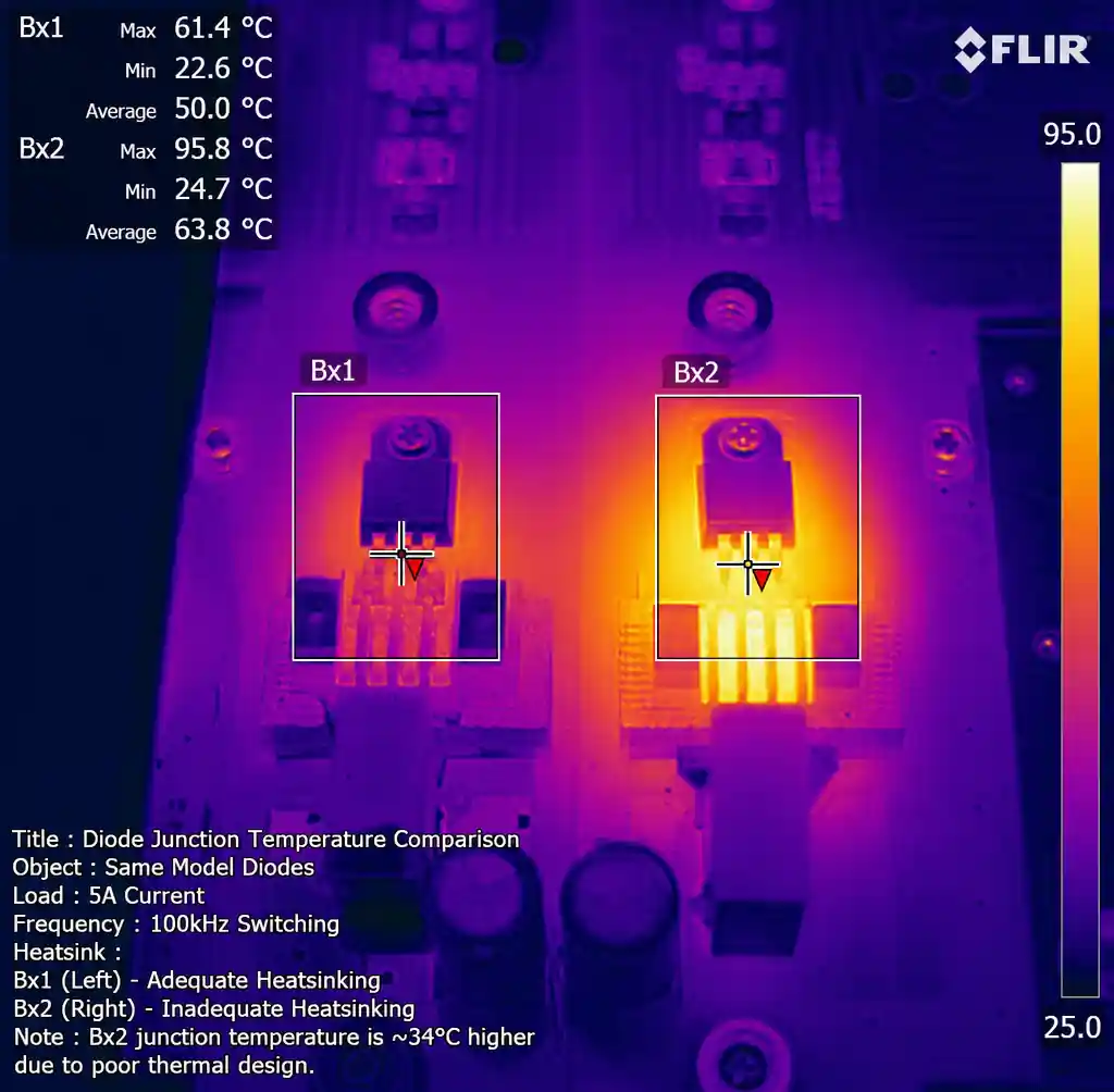 Thermal imaging showing diode temperature with and without proper heatsinking
Proper thermal design calculates worst-case dissipation at maximum current and temperature, then selects heatsinks to maintain Tj below 125°C. For 5W above, achieving 125°C in 50°C ambient requires (125-50)/5 = 15°C/W total thermal resistance.
Schottky diodes face thermal challenges from temperature-dependent leakage doubling every 10°C. At 25°C, a 40V Schottky leaks 0.1mA (4mW). At 125°C, leakage reaches 1.6mA (64mW), risking thermal runaway.
Power Dissipation Examples
| Application | Diode | Conduction | Switching | Total | Thermal Solution |
|---|---|---|---|---|---|
| 5A @ 60Hz | Fast Recovery | 5.0W | Negligible | ~5W | Small heatsink |
| 5A @ 100kHz | Schottky | 1.5W | <0.5W | ~2W | PCB copper |
| 5A @ 100kHz | Fast Recovery | 5.0W | 8.0W | ~13W | Large heatsink + fan |
When sourcing through product categories, thermal performance often matters more than cost. A $0.50 Schottky eliminating a $2.00 heatsink provides better total cost than a $0.15 standard rectifier requiring thermal management.
Application-Specific Selection Guide
Selecting diodes requires matching specifications to requirements beyond voltage and current. The decision starts with operating frequency, then considers voltage, current, thermal constraints, and cost.
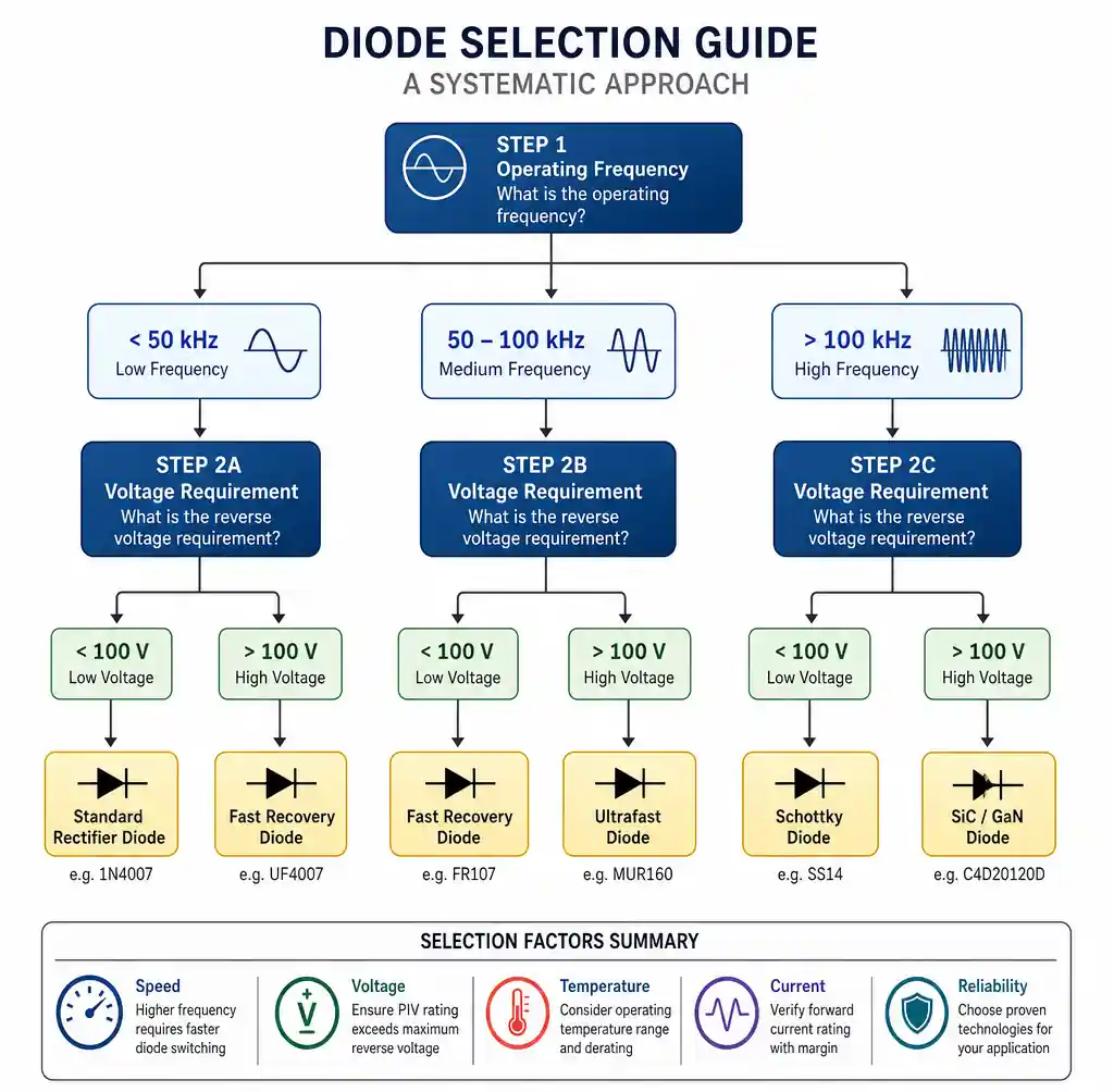 Diode selection decision tree based on frequency and voltage requirements
Rectification Applications
Line-frequency (50-60Hz) rectification uses fast recovery or standard rectifiers for best cost-performance. Slow switching makes reverse recovery irrelevant. A 10A bridge at 60Hz dissipates ~7W with 0.7V forward drop—manageable with modest heatsinking.
Switch-mode power supplies (20-200kHz) require careful selection. Below 50kHz, fast recovery works if trr < 10% of switching period. Above 50kHz, Schottky enables >90% efficiency.
High-frequency applications (>200kHz) demand Schottky unless voltage exceeds Schottky ratings. RF rectification, envelope detectors, and resonant converters need near-zero reverse recovery.
Protection Applications
Voltage clamping requires Zener or TVS diodes. Select Zener voltage 15-20% above maximum normal operation but below damage thresholds. A 12V rail with ±5% regulation uses 15V or 16V Zener without nuisance conduction.
Current limiting or series resistance prevents Zener destruction during sustained overvoltage. A 1W Zener handles peaks for milliseconds but fails at continuous high power.
Back-EMF suppression across inductive loads traditionally uses standard rectifiers. However, Schottky provides faster load release due to lower forward voltage.
Selection Matrix
| Requirement | First Choice | Alternative | Avoid |
|---|---|---|---|
| <50kHz, <100V | Fast Recovery | Schottky (low voltage) | Standard rectifier |
| >100kHz, <60V | Schottky | SiC Schottky (high temp) | Fast recovery |
| >100kHz, >100V | SiC Schottky | Fast recovery + snubber | Standard Schottky |
| Voltage regulation | Zener (matched) | TL431 reference | Rectifier types |
| Overvoltage clamping | TVS or Zener | Zener array | Rectifiers |
When working with manufacturers, specify actual requirements (frequency, voltage, current, thermal) to enable better recommendations.
Common Selection Mistakes
The most frequent error is using voltage and current ratings as sole criteria while ignoring application-specific parameters. Specifying a "600V, 5A diode" without mentioning 100kHz switching will likely yield a 200ns fast recovery diode causing 8-10W switching losses.
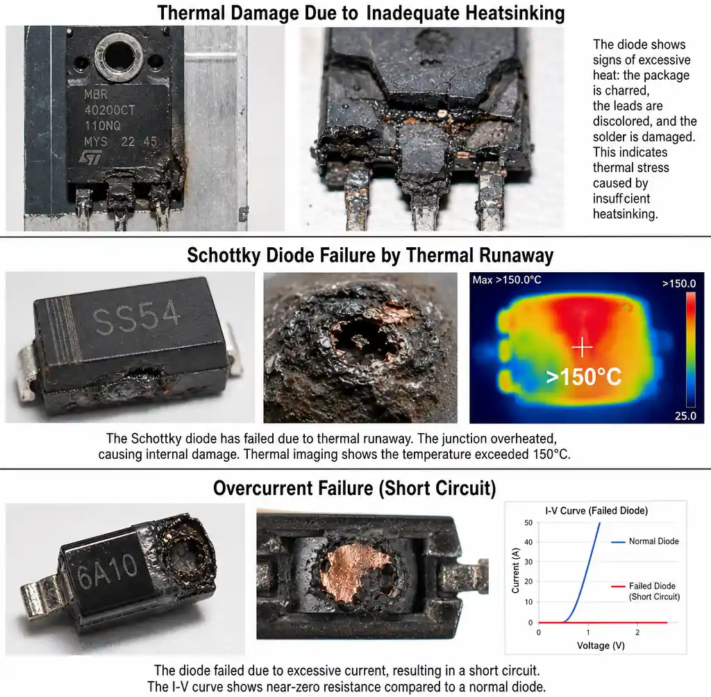 Common diode failure modes showing thermal damage and leakage effects
Ignoring Reverse Recovery in High-Frequency Circuits: Fast recovery diodes adequate at 20kHz become thermal problems at 200kHz. Use Schottky above 50kHz, or implement synchronous rectification with MOSFETs if voltage exceeds Schottky ratings.
Schottky in High-Temperature or High-Voltage: Schottky leakage increases exponentially with temperature, causing thermal runaway above 125°C. A 40V Schottky with 0.1mA leakage at 25°C reaches 10mA at 150°C, dissipating 400mW. For >100°C ambient or >100V reverse voltage, use fast recovery or SiC Schottky diodes.
Using Zener for Rectification: Substituting a Zener as a rectifier clamps voltage at the Zener breakdown rather than rectifying. A 12V Zener in a rectifier position clamps output to 12V regardless of input, preventing DC voltage generation.
Inadequate Thermal Design: Calculating at room temperature and typical current while ignoring worst-case conditions leads to field failures. Always calculate at Tj = 125°C with maximum rated current and worst-case ambient. If Tj approaches 150°C, the design lacks margin.
Overlooking Surge and Peak Current: Datasheets specify average (IF), peak repetitive (IFRM), and surge current (IFSM). A 3A average diode might have 30A IFRM and 100A IFSM ratings. Design for actual waveforms. For cost savings initiatives, avoiding these mistakes prevents expensive redesigns.
FAQ
Q: Can I use a Schottky diode instead of a fast recovery diode in a 300V application?
Standard silicon Schottky diodes are unsuitable for 300V—ratings typically max at 100-200V. Silicon carbide (SiC) Schottky diodes reach 1200V with low forward voltage and near-zero reverse recovery. SiC costs 3-5x more but eliminates switching losses and allows smaller magnetics.
Q: Why use multiple diodes in series for high-voltage applications?
Series diodes share reverse voltage when exceeding individual ratings. A 600V application might use two 400V diodes with voltage-balancing resistors. Forward drops sum, so three 1V diodes create 3V total drop.
Q: What's the difference between Zener and TVS diodes?
TVS (Transient Voltage Suppressor) diodes handle high-energy transients with faster response (<1ns vs 1-5ns) and higher peak current (hundreds of amps). Zeners suit steady-state regulation; TVS protects against ESD, lightning, and inductive spikes.
Q: How do I determine required Zener power rating?
Calculate I_max = (V_in_max - V_zener) / R_series. Power is P = V_zener × I_max. Select 2x calculated power for thermal margin. Example: 24V input, 15V Zener, 100Ω resistor yields I_max = 90mA, P = 1.35W, requiring 2W or 3W rating.
Q: Can fast recovery diodes work at 500kHz?
Fast recovery diodes become inefficient above 200kHz—switching losses often exceed conduction losses, causing thermal issues. At 500kHz, Schottky diodes are required for <200V. Higher voltages need synchronous rectification with MOSFETs or SiC Schottky.
Q: Do Schottky diodes require special handling?
Standard ESD precautions suffice. However, they're sensitive to reverse voltage transients. Brief reverse overvoltage causes permanent leakage increase. Use current-limited supplies during prototyping.
Q: Why does my Schottky get hot at low current?
Excessive heating indicates reverse leakage from elevated temperature (thermal runaway) or voltage exceeding ratings. Measure reverse voltage during operation—transients can momentarily exceed ratings. Add snubber circuits (RC damping) or select higher voltage ratings.
Q: What's the practical frequency limit for fast recovery diodes?
Reverse recovery should be <10% of switching period. A 200ns diode works adequately to 50kHz (period = 20µs). From 50-100kHz, efficiency degrades but may be acceptable. Above 100kHz, fast recovery is generally unsuitable.
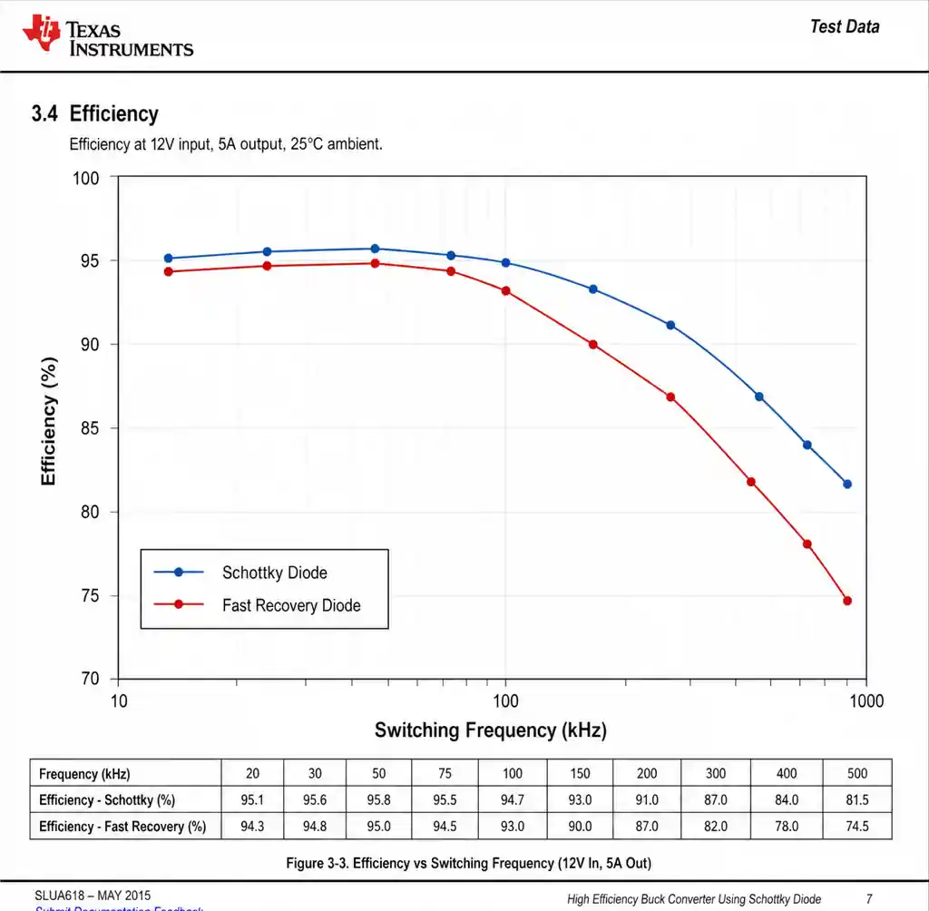 Efficiency measurement comparison between Schottky and fast recovery diodes at various frequencies
Conclusion
Diode selection determines circuit efficiency, thermal performance, and reliability. Schottky diodes excel in low-voltage, high-frequency applications with 0.15-0.45V forward drop and near-zero reverse recovery. Fast recovery diodes bridge standard rectifiers and Schottky, offering 200-1200V ratings with acceptable switching for frequencies to 100kHz. Zener diodes provide voltage regulation and clamping—never substitute for rectification.
Three critical parameters drive selection: operating frequency, voltage rating, and thermal environment. Verify actual specifications—ignore marketing claims. A 500ns fast recovery diode fails at 200kHz, and a 125°C-rated Schottky experiences thermal runaway in 100°C ambient.
For procurement teams sourcing across product lines, understanding these distinctions prevents costly redesigns and field failures from price-only selection. The right diode adds pennies to BOM while enabling designs meeting efficiency targets without oversized thermal management. When specifications and availability matter, experienced distributors understanding application requirements deliver better outcomes than parametric search alone.
