




High Voltage Resistor Selection for kV Applications
High voltage resistors operate in extreme electrical environments where component failures can cascade into system-wide breakdowns or safety hazards. In power supplies handling voltages above 1kV, medical imaging equipment operating at tens of kilovolts, and industrial test systems pushing beyond 100kV, resistor selection demands more than checking resistance values. A single arc-over event or voltage coefficient drift can compromise measurement accuracy or destroy downstream components.
If you need to specify high voltage resistors for kV applications, then you must understand voltage ratings, pulse withstand capability, voltage coefficient effects, and safety spacing requirements. This guide draws from industry specifications to help you select resistors that maintain precision and reliability under extreme voltage stress.
Table of Contents
- Understanding High Voltage Resistor Requirements
- Critical Voltage Parameters
- Resistor Technologies for High Voltage
- Voltage Coefficient and Pulse Withstand
- Series and Parallel Configurations
- Safety Spacing and Creepage
- Application-Specific Selection
- FAQ
- Conclusion
Understanding High Voltage Resistor Requirements
High voltage resistors are engineered to handle voltages typically above 1kV, often extending into tens or hundreds of kilovolts. Unlike standard resistors where power dissipation drives thermal design, high voltage applications introduce arc-over risk, voltage coefficient effects, and insulation breakdown as primary failure mechanisms.
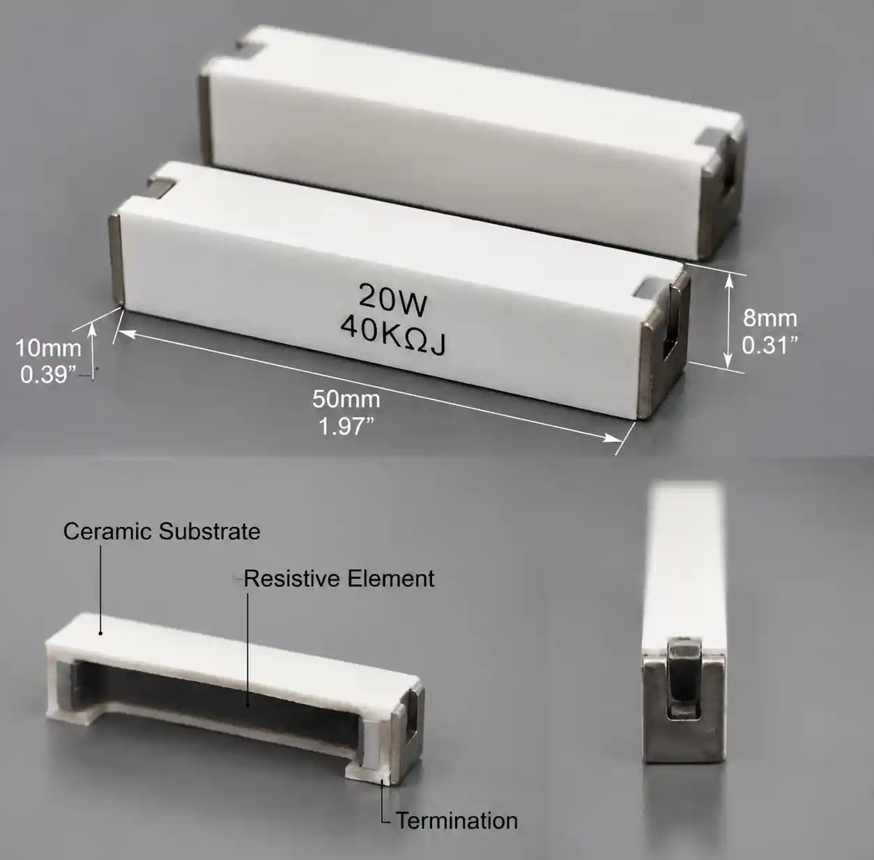 High voltage resistor showing electric field distribution and construction
At 10kV across a 10mm component body, the electric field reaches 1kV/mm—approaching the breakdown strength of many insulating materials. Component geometry, resistive element construction, and surface treatment determine whether a resistor can reliably operate at its rated voltage or suffers flashover along its surface.
You can source high voltage resistors in thick film, thin film, wirewound, and carbon composition technologies. Each offers distinct voltage handling characteristics, with thick film dominating cost-sensitive applications, thin film providing superior stability, and wirewound excelling in pulse energy absorption.
Critical Voltage Parameters
Selecting high voltage resistors requires evaluating multiple voltage specifications that interact to define safe operating boundaries. Maximum working voltage, arc-over voltage, and pulse withstand capability each address distinct failure modes.
Maximum Working Voltage and Arc-Over
Maximum working voltage specifies the highest continuous DC or AC RMS voltage a resistor can sustain without degradation. For applications operating at 10kV, specify resistors rated for at least 12-15kV to provide safety margin against transients.
Arc-over voltage represents the voltage at which electrical discharge occurs along the resistor's surface or through air gaps between terminations. Surface contamination, humidity, and altitude reduce arc-over voltage from datasheet values. Maintain working voltage below 60% of rated arc-over voltage for critical applications.
Dielectric Withstand Voltage
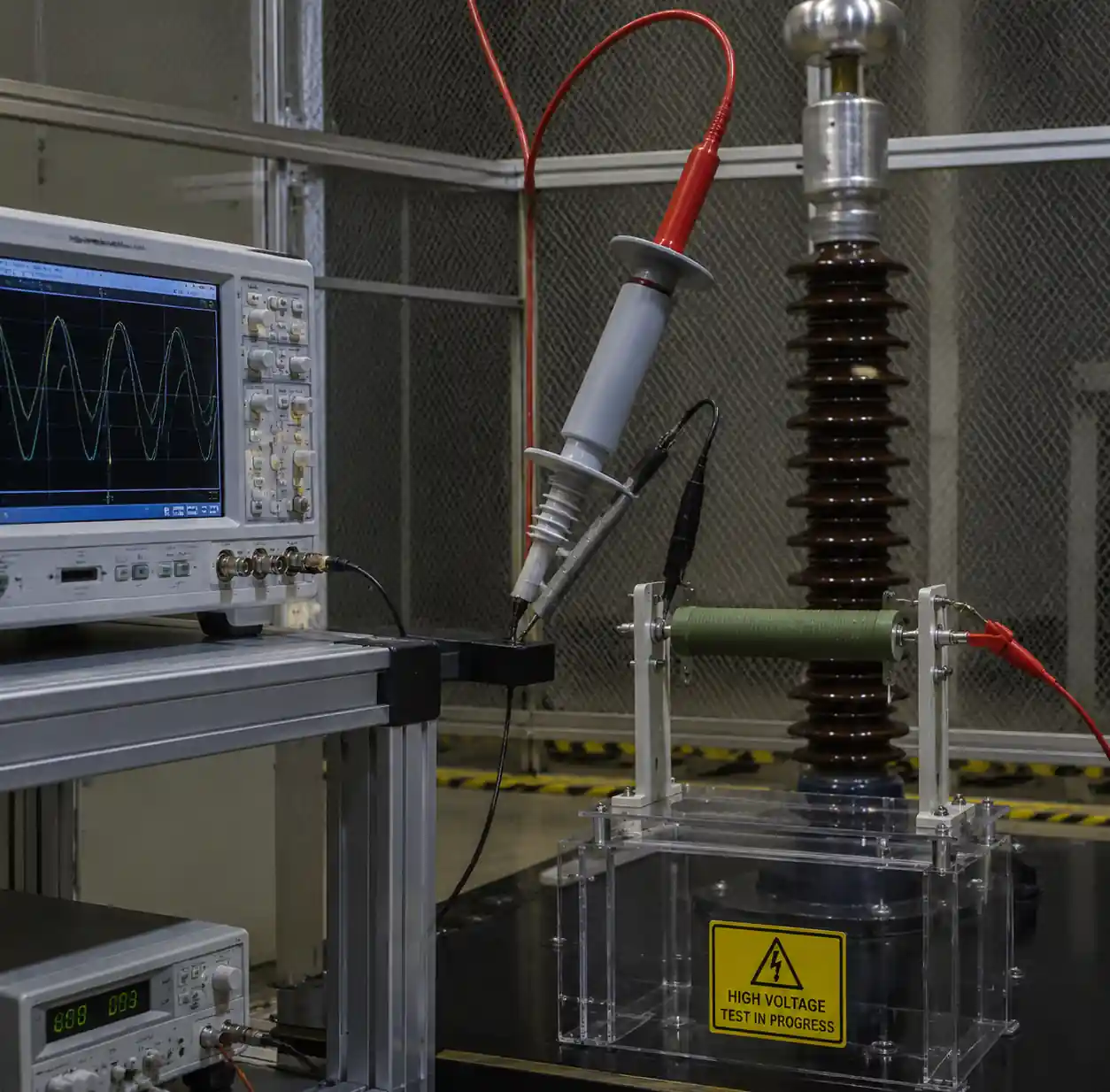 High voltage testing equipment showing dielectric withstand and arc-over voltage measurement
Dielectric withstand voltage tests the insulation system's ability to prevent breakdown through the resistor body. Testing per IEC 60115-1 applies 1.5× rated voltage for one minute without flashover. This parameter becomes crucial in medical device applications where patient safety depends on robust insulation.
| Parameter | Definition | Typical Safety Margin | Test Standard |
|---|---|---|---|
| Max Working Voltage | Continuous operating voltage | 80% of rated | IEC 60115-1 |
| Arc-Over Voltage | Surface flashover threshold | 60% of rated | IEC 60664-1 |
| Dielectric Withstand | Insulation breakdown voltage | 67% of test voltage | IEC 60115-1 |
| Pulse Withstand | Transient voltage capability | Per pulse energy spec | IEC 61000-4-5 |
Resistor Technologies for High Voltage
Different resistor technologies offer distinct advantages for high voltage applications, with selection driven by voltage rating requirements, precision needs, and pulse energy absorption capability.
Thick Film Resistors
Thick film technology dominates high voltage applications requiring voltages from 1kV to 35kV in compact packages. Manufacturers print resistive paste containing glass frit and metal oxides onto ceramic substrates, then fire at temperatures exceeding 850°C. This process produces resistors capable of withstanding 3-5kV per centimeter of body length.
Thick film resistors offer resistance values from 1MΩ to 10GΩ with tolerances down to 0.5% and voltage coefficients below 10 ppm/V. Their monolithic construction provides excellent pulse withstand capability. You can source thick film high voltage resistors for power supply voltage dividers and industrial measurement systems.
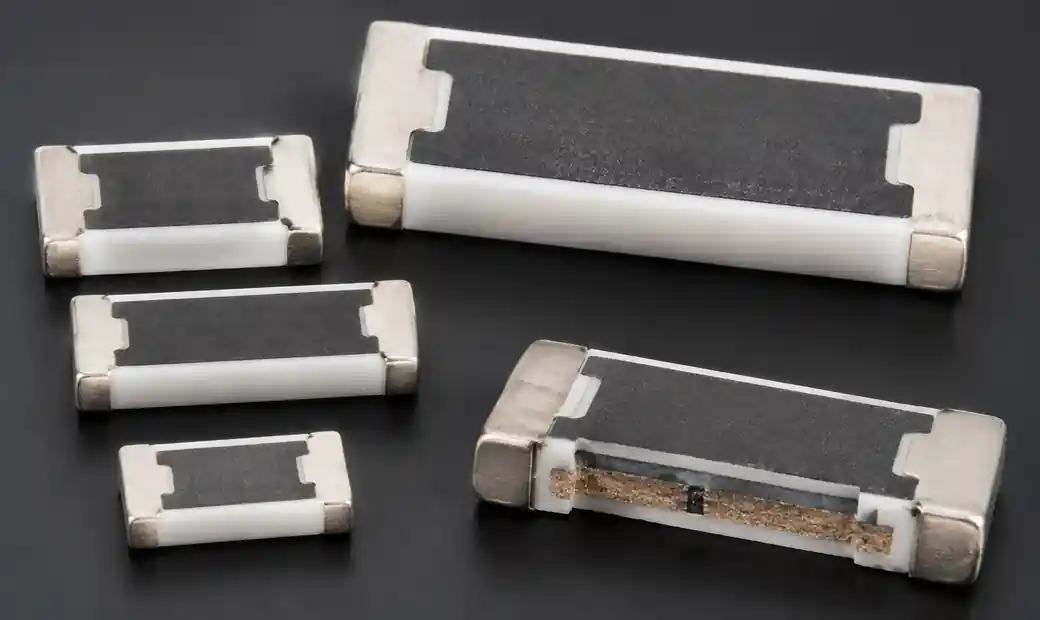 Thick film high voltage resistors showing ceramic substrate and resistive paste construction
Thin Film and Wirewound Resistors
Thin film resistors provide superior stability with voltage coefficients below 1 ppm/V and temperature coefficients down to ±5 ppm/°C. Maximum voltage typically ranges from 200V to 5kV. Applications requiring both high voltage and sub-0.1% accuracy, such as precision voltage dividers in medical imaging, justify the higher cost.
Wirewound resistors excel in pulse energy absorption with inherent pulse withstand capability 10-100× higher than film types. Voltage ratings extend beyond 100kV in series-connected assemblies for high voltage test equipment and X-ray power supplies.
| Technology | Pulse Energy | Voltage Range | Typical VCR | Best Applications |
|---|---|---|---|---|
| Thick Film | High (10-100J) | 1-35kV | 5-25 ppm/V | General purpose HV, surge protection |
| Thin Film | Low (0.1-1J) | 0.2-5kV | <1 ppm/V | Precision measurement, voltage dividers |
| Wirewound | Very High (100-1000J) | 5-100kV+ | 10-50 ppm/V | Pulse applications, X-ray power supplies |
Voltage Coefficient and Pulse Withstand
Voltage coefficient of resistance (VCR) quantifies how resistance changes with applied voltage, typically specified in ppm/V. A resistor with 10 ppm/V coefficient operating at 10kV experiences 1% total resistance shift. For voltage divider applications requiring 0.1% accuracy, specify VCR below 10 ppm/V.
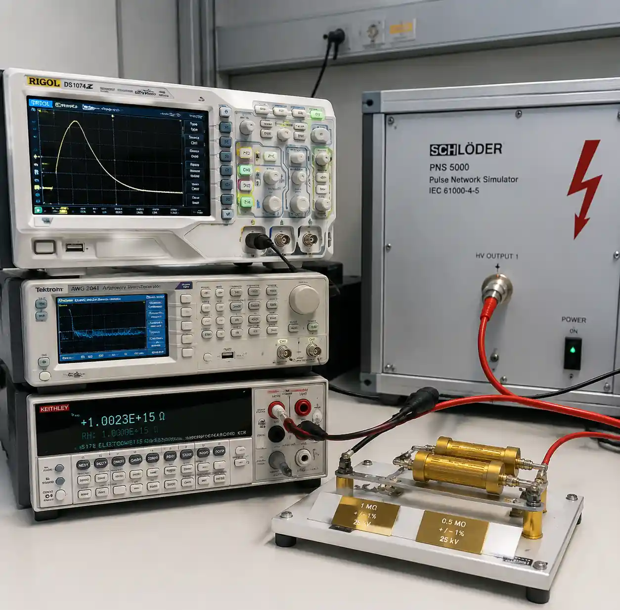 Voltage coefficient and pulse withstand testing equipment for high voltage resistors
Thick film resistors exhibit VCR values between 5-50 ppm/V depending on composition. Thin film types achieve below 1 ppm/V through tighter material control. Precision voltage dividers benefit from matched resistor sets where VCR values track across temperature and voltage.
Pulse Energy Absorption
High voltage circuits experience transient overvoltages from switching events, lightning-induced surges, and ESD strikes exceeding steady-state voltage by 2-10×. Resistors must absorb pulse energy without exceeding temperature limits causing element cracking or insulation breakdown.
Manufacturers specify pulse withstand as peak voltage for standard waveforms (8/20 µs or 1.2/50 µs per IEC 61000-4-5) or as maximum pulse energy in joules. Specify resistors tested for at least 100 pulses at rated energy to ensure robust field operation.
Series and Parallel Configurations
Single resistors rarely achieve the voltage ratings or power dissipation required for extreme high voltage applications. Series configurations distribute total voltage across multiple elements, reducing individual component stress.
Series Connection Considerations
For a 50kV application using ten 10MΩ resistors rated at 10kV each, voltage division provides a 2× safety margin on each component. However, resistance tolerance affects voltage distribution—±5% tolerance creates voltage imbalances. Specify matched resistor sets with ±1% tolerance for critical applications.
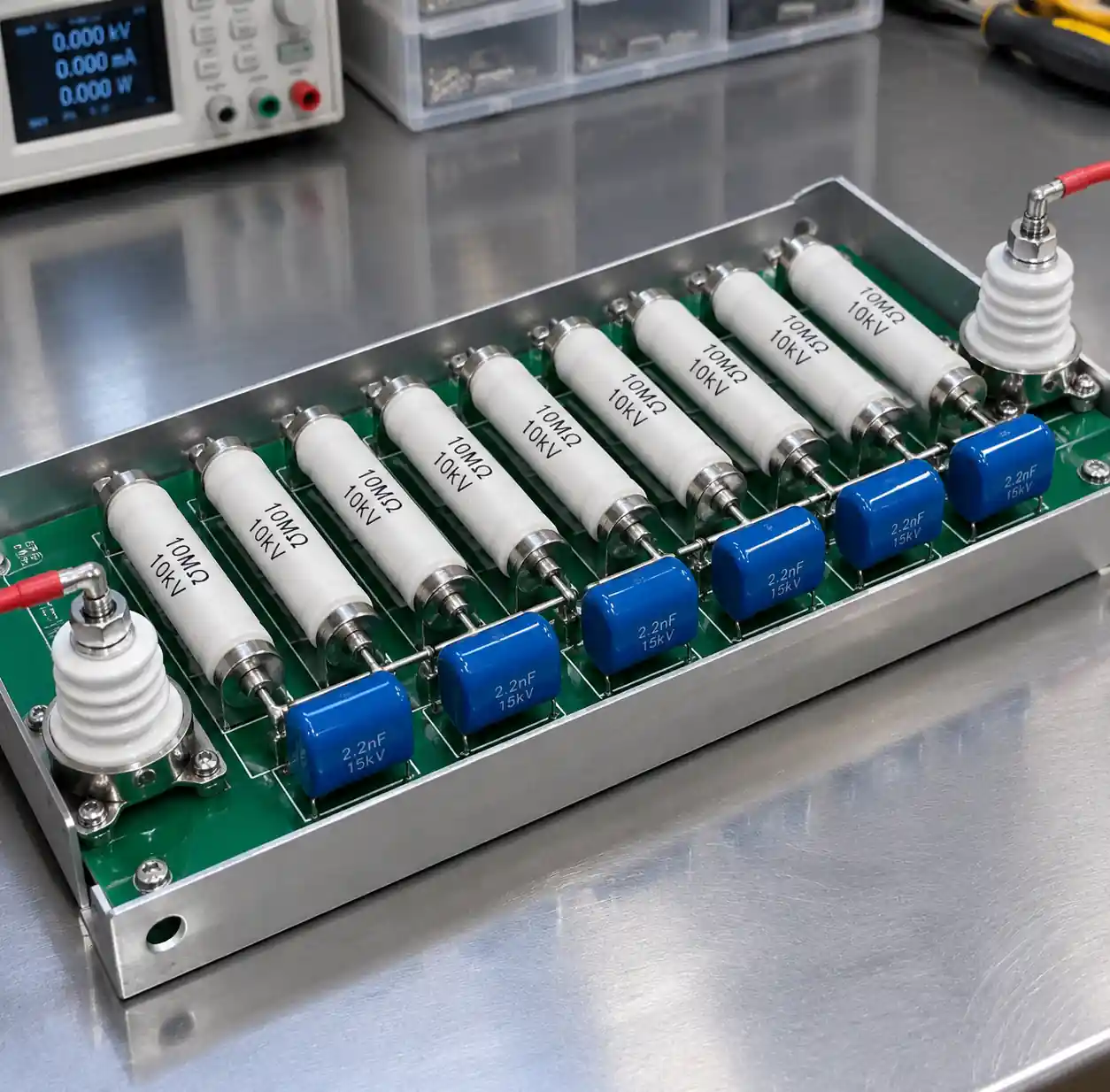 Series and parallel high voltage resistor configurations for voltage division
Parasitic capacitance creates dynamic voltage distribution issues during transients. Adding small capacitors (10-100pF) in parallel with each series resistor balances AC voltage distribution and protects against transient overvoltage.
You can source high voltage resistor assemblies with factory-matched series-parallel configurations for applications requiring precise voltage division and high power handling.
Safety Spacing and Creepage
High voltage resistor installation requires careful attention to clearance and creepage distances preventing arc-over between energized components.
Clearance and Creepage Requirements
Clearance represents the shortest distance through air between conductors. IEC 60664-1 specifies minimum clearances based on working voltage and pollution degree. For 10kV working voltage in pollution degree 2 (normal industrial), minimum clearance reaches 25mm.
Creepage distance measures the path along insulating surfaces. IEC 60664-1 specifies 45mm creepage for 10kV in pollution degree 2—significantly longer than clearance. Resistor mounting orientation affects contamination accumulation, with vertical mounting preventing moisture and dust from bridging insulating surfaces.
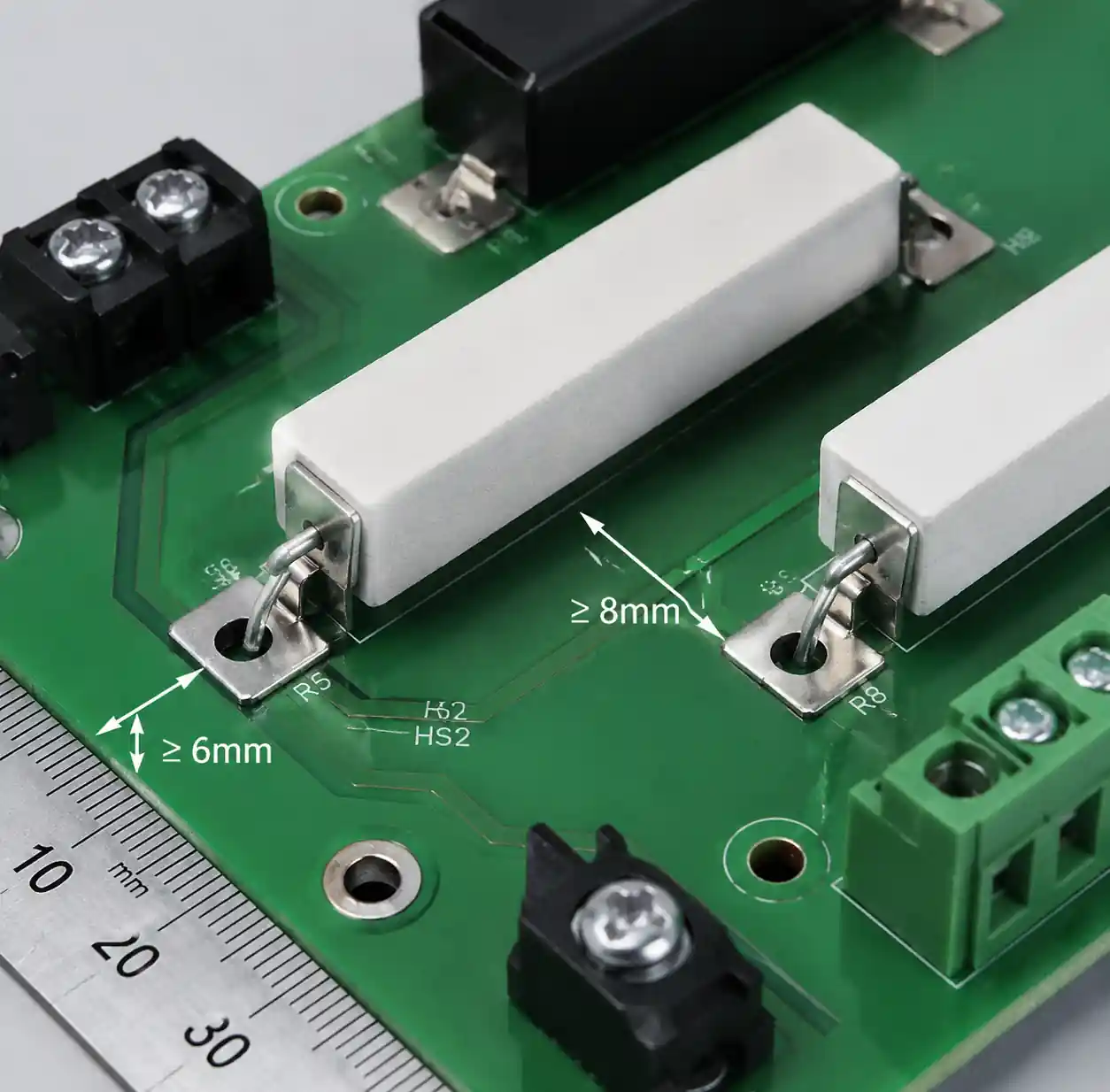 High voltage resistor installation showing clearance and creepage distance requirements
Altitude reduces air density and decreases breakdown voltage. Applications operating above 2000m require clearance multipliers from 1.10× at 3000m to 2.00× at 9000m.
Application-Specific Selection
Different applications impose distinct requirements driving resistor technology selection and specification priorities.
Medical Imaging Equipment
X-ray generators and CT scanners operate at voltages from 40kV to 150kV with strict safety requirements per IEC 60601-1. Voltage dividers require <0.1% accuracy maintained across temperature and voltage ranges. Specify thin film or precision thick film resistors with VCR below 5 ppm/V and TCR below ±25 ppm/°C.
Isolation requirements demand dual-insulated construction with creepage distances calculated for pollution degree 2. You can source medical-grade electronic components with necessary safety certifications.
Industrial Power Supplies
Switching power supplies operating from 1kV to 10kV use high voltage resistors for voltage sensing, current limiting, and discharge. These applications demand robust pulse withstand capability. Thick film resistors rated for pulse energy absorption per IEC 61000-4-5 level 4 (±4kV, 2kA) provide adequate protection.
Power dissipation becomes critical in current sensing where resistors must continuously absorb significant power. Derating to 50% of rated power at maximum ambient temperature ensures reliable operation.
FAQ
What voltage rating should I specify for a resistor in a 10kV application?
Specify resistors rated for at least 12-15kV to provide 20-50% margin above working voltage. This margin accounts for transient overvoltages, voltage coefficient effects, and derating for temperature and altitude. Critical applications should maintain working voltage below 70% of rated voltage.
How does voltage coefficient affect measurement accuracy?
Voltage coefficient (VCR) causes resistance to change with applied voltage. A 10 ppm/V coefficient produces 0.01% change per volt, accumulating to 1% error at 10kV. For precision applications requiring <0.1% accuracy, specify VCR below 10 ppm/V.
Can I use multiple standard resistors in series instead of specialized high voltage types?
Yes, but with careful design. Series connection can achieve 10-20kV total rating. However, resistance tolerance causes voltage imbalance, and parasitic capacitance creates transient voltage concentration. Add small equalizing capacitors across each resistor and specify tight tolerance matching.
What is the difference between arc-over voltage and dielectric withstand voltage?
Arc-over voltage represents flashover along the resistor's surface through air. Dielectric withstand voltage tests insulation breakdown through the resistor body. Both must exceed working voltage with appropriate safety margins—typically operate below 60% of arc-over voltage.
How do I calculate required pulse withstand capability?
Identify maximum expected pulse voltage and waveform (8/20 µs or 1.2/50 µs per IEC 61000-4-5). Calculate pulse energy from E = V²t/R. Specify resistors with pulse energy rating 2-3× calculated maximum to account for repetitive stress.
What clearance and creepage distances are required for 10kV applications?
Per IEC 60664-1 for pollution degree 2, minimum clearance is 25mm and creepage is 45mm at 10kV. These values assume operation below 2000m altitude. Higher altitudes require increased clearance.
Conclusion
High voltage resistor selection for kV applications requires balancing voltage rating, pulse withstand capability, voltage coefficient, and safety spacing requirements. Understanding how these specifications interact determines whether your design achieves the required accuracy, reliability, and safety margins.
If you need reliable electronic components with proper high voltage specifications, Hitop Tech offers comprehensive procurement services with global sourcing network across Asia, Europe, North America, and Africa. Our authorized distributor relationships ensure authentic components meeting IEC, UL, and application-specific safety standards. We specialize in sourcing electronic components for medical device, industrial power supply, and high voltage test applications.
Contact us today for electronic component sourcing, technical specification verification, and supply chain optimization services tailored to your high voltage application requirements.
