


Junction Box Engineering Guide: Design Principles, Selection Criteria, and Installation Best Practices
A junction box is a fundamental enclosure in electrical systems used to contain, protect, and manage wire splices. While often considered a basic component, improper selection or installation can lead to overheating, insulation failure, and fire hazards. This guide approaches junction boxes from an engineering perspective—covering enclosure physics, compliance constraints, sizing calculations, ingress protection, and failure modes—so designers and technicians can make informed decisions in residential, commercial, and industrial environments.
Table of Contents
- 1. Definition and Functional Role
- 2. Electrical and Mechanical Functions
- 3. Internal Architecture and Components
- 4. Classification of Junction Boxes
- 5. Environmental Considerations: Indoor vs Outdoor
- 6. Engineering Sizing Methodology
- 7. Wiring Methodology and Best Practices
- 8. Common Failure Modes and Design Mistakes
- 9. Junction Box vs Electrical Box (Engineering Comparison)
- 10. When to Engage a Licensed Electrician
- 11. FAQ
1. Definition and Functional Role
A junction box (J-box) is a protective enclosure used to house electrical connections (splices, taps, or terminations). It ensures that conductors are electrically insulated, mechanically secured, and environmentally protected.
From a system design perspective, junction boxes act as distributed interconnection nodes, improving maintainability, fault isolation, and system modularity.
2. Electrical and Mechanical Functions
2.1 Electrical Protection
- Prevents arc exposure during fault conditions
- Reduces short-circuit probability
- Supports grounding continuity (especially for metal enclosures)
2.2 Thermal Management
Electrical connections generate heat due to contact resistance:
P = I²R
A properly sized enclosure ensures sufficient heat dissipation and reduces thermal aging of insulation materials.
2.3 Mechanical Retention
- Cable clamps prevent mechanical stress on terminations
- Maintains long-term connection integrity
3. Internal Architecture and Components
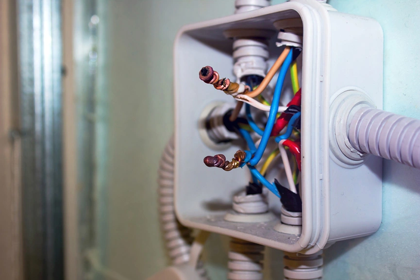
3.1 Conductors
Copper or aluminum wires with insulation ratings such as PVC or XLPE. Selection must comply with ampacity standards.
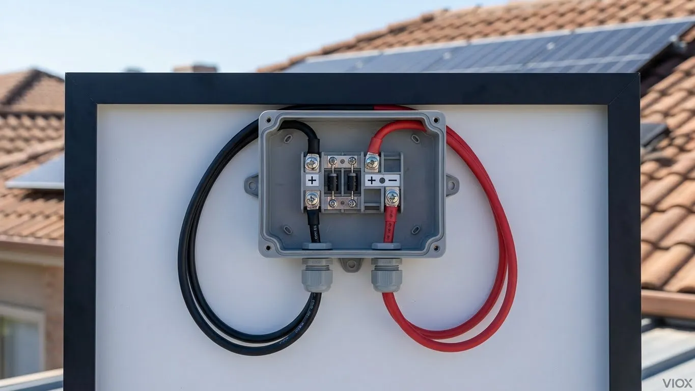
3.2 Connection Interfaces
- Wire nuts (twist-on connectors)
- Terminal blocks (screw or spring clamp type)
3.3 Grounding System
Essential for safety. Metal enclosures must be bonded to ground to provide a low-resistance fault path.
3.4 Cable Entry System
Includes glands or clamps that provide strain relief and environmental sealing.
4. Classification of Junction Boxes
4.1 By Material
- Thermoplastic (PVC/ABS): lightweight, corrosion-resistant, non-conductive
- Metal (steel/aluminum): high strength, suitable for industrial environments
4.2 By Mounting Method
- Surface-mounted: easy access, suitable for retrofits
- Flush-mounted: concealed installation for clean appearance
4.3 By Protection Level
- Standard: IP20–IP40
- Sealed: IP65–IP68
4.4 By Function
- Splice boxes
- Terminal boxes
- Distribution junction boxes
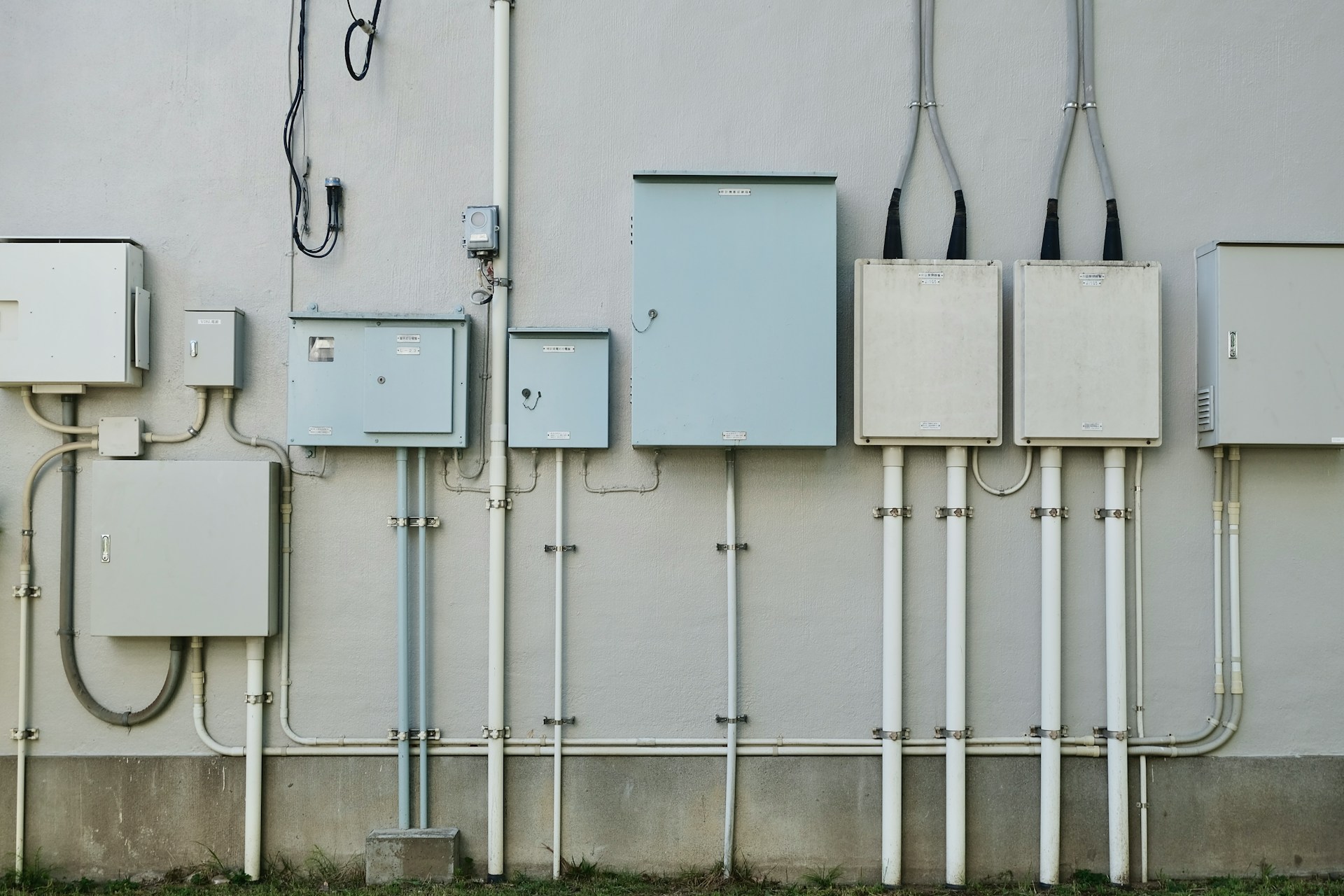
5. Environmental Considerations: Indoor vs Outdoor
| Parameter | Indoor | Outdoor |
|---|---|---|
| IP Rating | IP20–IP40 | IP65+ |
| Material | Plastic | UV-resistant plastic / metal |
| Sealing | Minimal | Gasket + cable gland |
| Thermal Exposure | Stable | Variable |
| Durability | Moderate | High |
Outdoor designs must consider UV degradation, thermal expansion cycles, and condensation effects.
6. Engineering Sizing Methodology
6.1 Volume Calculation
Box sizing must follow conductor fill rules (e.g., NEC guidelines). Each conductor occupies a defined volume depending on wire gauge.
6.2 Design Considerations
- Avoid exceeding 70–80% fill capacity
- Increase size for high current or multiple splices
- Allow space for terminal blocks and connectors
6.3 Thermal Impact
Overcrowding reduces airflow and increases internal temperature, accelerating insulation failure.
7. Wiring Methodology and Best Practices
Step-by-Step Process
- Turn off power (apply lockout/tagout if required)
- Strip insulation using proper tools
- Connect wires using appropriate connectors
- Ensure tight and secure connections
- Arrange wires to avoid stress and crowding
- Close and seal the enclosure properly
8. Common Failure Modes and Design Mistakes
8.1 Overfilling
Leads to overheating and insulation degradation
8.2 Loose Connections
Causes arcing, voltage drops, and heat buildup
8.3 Incorrect Enclosure Type
Using indoor boxes outdoors results in moisture ingress
8.4 Poor Accessibility
Violates electrical codes and complicates maintenance
8.5 Grounding Issues
Increases risk of electric shock and improper fault clearing
9. Junction Box vs Electrical Box (Engineering Comparison)
| Feature | Junction Box | Electrical Box |
|---|---|---|
| Main Function | Wire splicing and protection | Device mounting |
| Usage | Connections only | Switches, outlets, fixtures |
| Accessibility | Must remain accessible | Accessible via device |
| Thermal Load | Higher | Moderate |
| Mechanical Role | Protection | Supports devices |
10. When to Engage a Licensed Electrician
Professional assistance is recommended when:
- Working with high-current circuits (>20A)
- Modifying existing wiring systems
- Observing signs like burn marks, tripping breakers, or unstable voltage
11. FAQ
Q1: What happens if a junction box is undersized?
It increases conductor density, leading to overheating, insulation damage, and potential fire hazards.
Q2: Can junction boxes be hidden inside walls?
They can be flush-mounted, but must remain accessible for inspection and maintenance.
Q3: Are metal boxes always better than plastic?
No. Metal offers strength and grounding, while plastic provides corrosion resistance and insulation. Selection depends on application.
Q4: What IP rating is required for outdoor use?
Typically IP65 or higher, depending on environmental exposure.
Q5: Why is grounding important in a junction box?
It provides a low-resistance path for fault current, enabling protective devices to operate effectively.
Conclusion
A junction box is a critical safety component in electrical systems. Proper selection and installation require evaluating electrical load, environmental conditions, thermal behavior, and regulatory compliance. Applying engineering principles ensures long-term reliability, safety, and maintainability of the electrical infrastructure.