




Medical Device Electronic Component Selection: The Definitive Guide for Hardware Engineers (2026)
A complete framework for selecting, qualifying, and managing electronic components in medical devices — from derating to obsolescence planning.
TL;DR: Component selection for medical devices isn't just about picking parts that meet the datasheet. It's a multi-dimensional discipline spanning safety classification, regulatory compliance, supply chain resilience, and lifecycle management. This guide covers every standard, strategy, and pitfall — including the brand-new AFNOR SPEC 2311 (2025) and the upcoming IEC 60601-1 4th Edition overhaul.
Table of Contents
- Why Component Selection Makes or Breaks Medical Devices
- The Regulatory Landscape: Standards That Govern Every Component Decision
- Component Safety Classification: Not All Parts Are Equal
- The Six Pillars of Medical Component Selection
- PCB Materials: The Foundation Beneath Every Component
- Creepage, Clearance, and EMC: When Physics Meets Regulation
- Derating: The Engineer's Safety Margin
- The BOM Lifecycle: From Selection to End-of-Life
- Common Mistakes That Trigger Audits, Recalls, and Redesigns
- The 2026 Checklist: A Practical Selection Workflow
- Frequently Asked Questions
- Key Takeaways
Why Component Selection Makes or Breaks Medical Devices
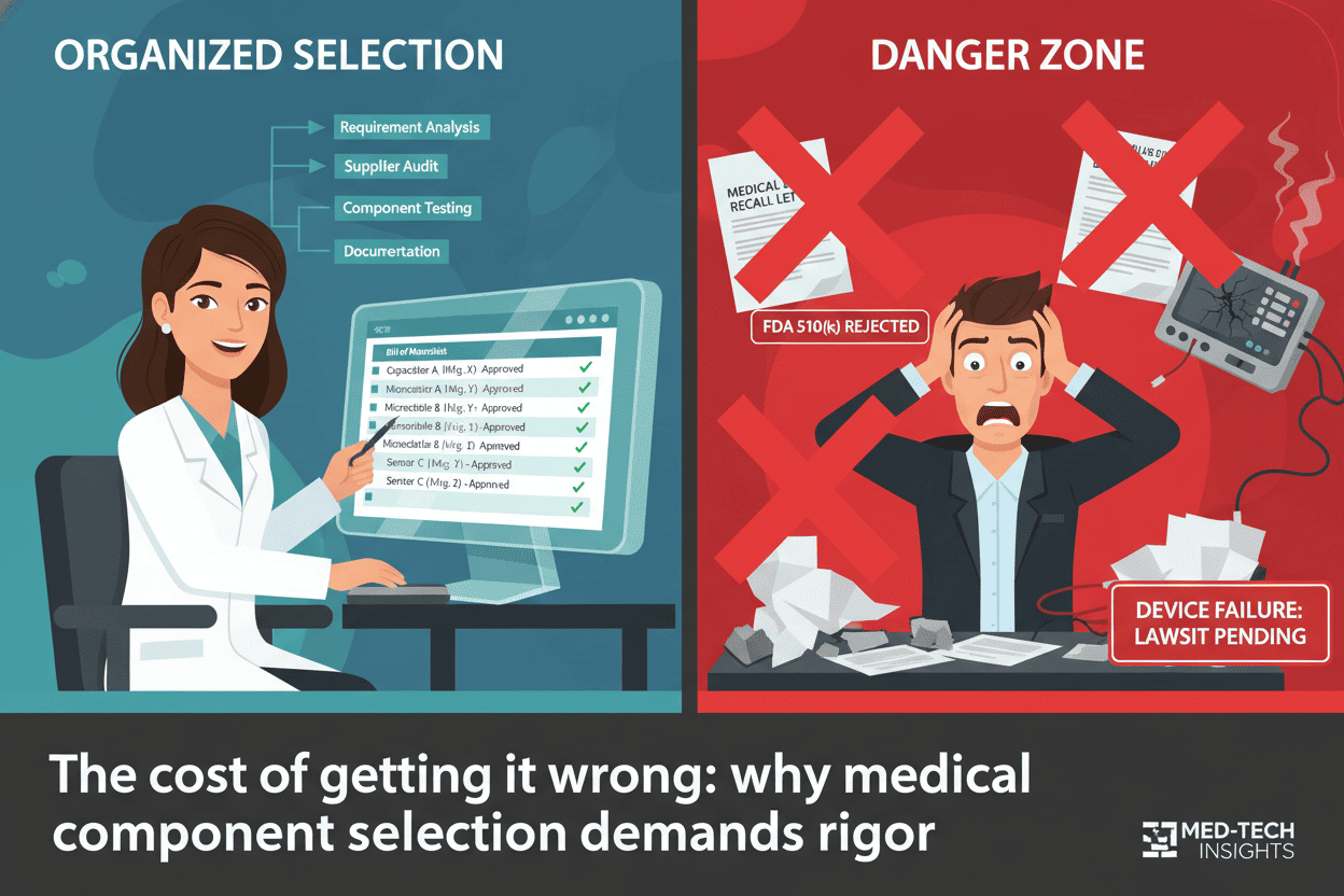
Every medical device begins its life in a BOM spreadsheet. But for medical hardware engineers, that spreadsheet carries a weight most consumer electronics engineers never feel: a single wrong component choice can trigger an FDA recall, cost tens of millions of dollars, and — most critically — put patient lives at risk.
According to FDA recall data, approximately 23% of medical device recalls trace back to circuit design defects, and roughly 28% of minimally invasive instrument failures stem from PCB performance degradation after repeated sterilization cycles. The PCB substrate alone, if found to contain heavy metal content exceeding 100 ppm of lead, has triggered full product recalls exceeding $30 million.
Component selection isn't a procurement activity. It's a safety-critical engineering discipline.
The Regulatory Landscape: Standards That Govern Every Component Decision
Before selecting a single resistor, you need to know which standards apply to your device class. The regulatory framework is dense — but it's also your best friend when justifying design decisions to auditors.
Core Standards at a Glance
| Standard | What It Governs | Why It Matters for Component Selection |
|---|---|---|
| IEC 60601-1 (3rd Ed. + Amd2) | Base safety for medical electrical equipment | Defines creepage/clearance, insulation, leakage current — directly dictates component voltage/power ratings |
| IEC 60601-1-2 (Ed. 4.1) | EMC for medical devices | Dictates EMI filtering component selection, shielding requirements |
| ISO 13485 | QMS for medical device manufacturers | Mandates supplier qualification, incoming inspection, traceability |
| ISO 14971 | Risk management | Drives safety classification of every component in the BOM |
| IPC Class 3 / IPC-A-600/610 | High-reliability PCB workmanship | Sets acceptance criteria for solder joints, annular rings, plating |
| FDA 21 CFR Part 820 | Quality System Regulation (US) | Requires design controls linking component selection to user needs |
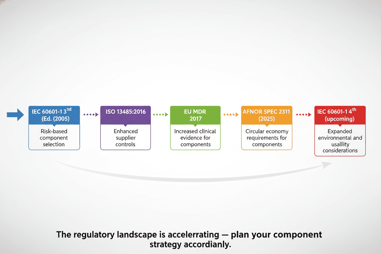
| EU MDR 2017/745 | European medical device regulation | Strengthens traceability and clinical evidence requirements |
| RoHS / REACH | Hazardous substance restrictions | Directly constrains material composition of components |
What's New in 2025-2026
Two landmark developments are reshaping the landscape:
AFNOR SPEC 2311 (Published March 2025). This is the first dedicated framework for qualifying electronic components in Active Implantable Medical Devices (AIMDs). Developed through the RECOME Project with ~60 industry stakeholders, it provides:
- Test protocols by component family (SMD resistors, ceramic capacitors, tantalum capacitors, inductors, ICs)
- Qualification test plan requirements with batch specs, sample sizes, and acceptance criteria
- Comprehensive environmental constraint coverage (humidity, chemical, mechanical, electrical, thermal, and radiative stresses)
If you're working on implantables, this spec is now effectively required reading.
IEC 60601-1 4th Edition (In Development). The most significant overhaul of the core medical safety standard in decades brings paradigm-shifting changes:
- Programmable Electrical Medical Systems (PEMS) elevated to a foundational requirement — covering FPGAs, ASICs, and all programmable electronics
- Mandatory cybersecurity framework added for the first time
- "Systems-level thinking" required from the start of product development
- Redundancy and architectural strategies explicitly addressed (common cause failures, systematic failures, maintainability)
- IT-network integration rules — manufacturers must provide technical specifications, qualification tests, and time synchronization mechanisms
Component Safety Classification: Not All Parts Are Equal
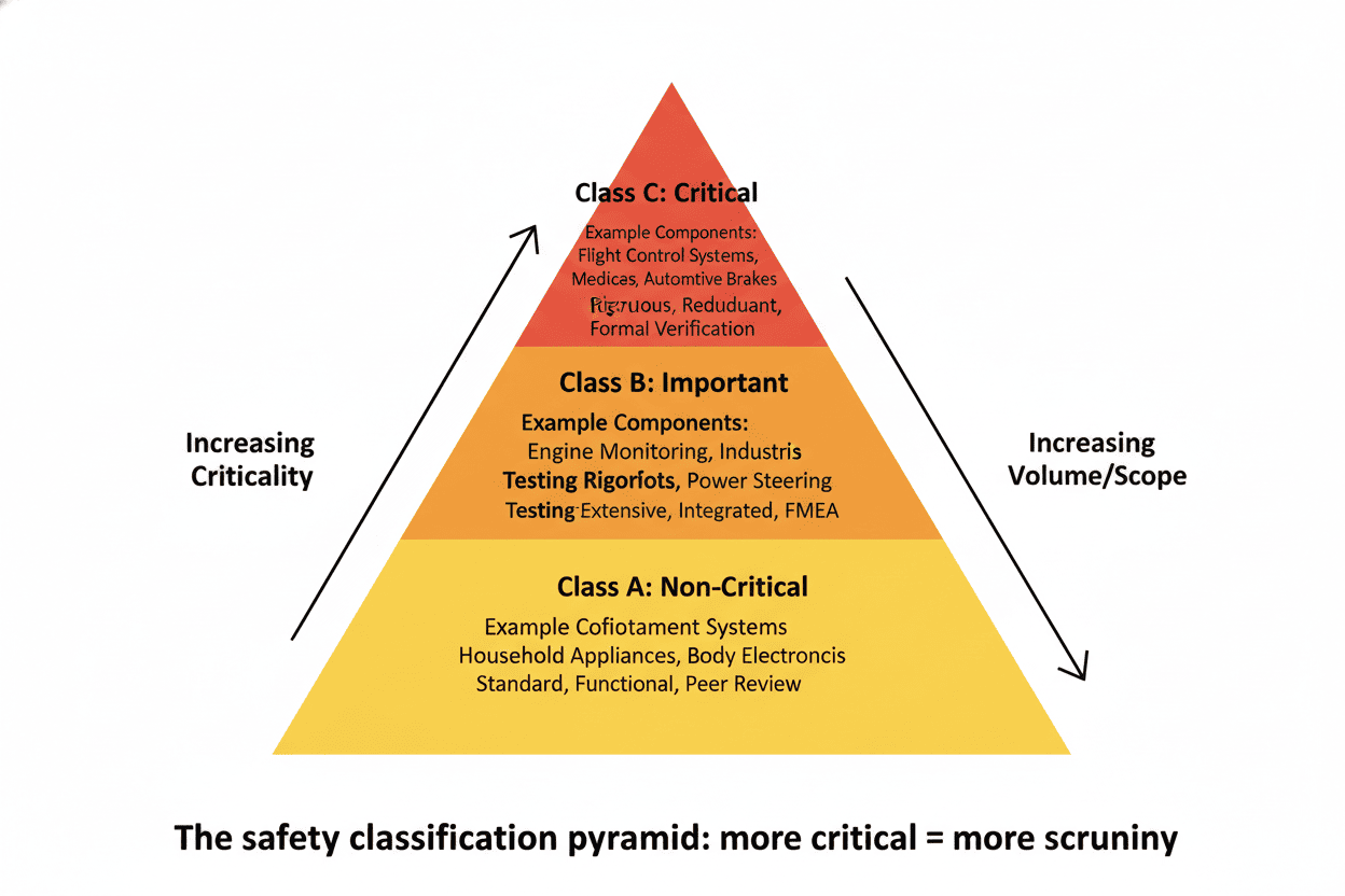
One of the most important (and often overlooked) pre-selection steps is classifying every component by safety criticality. ISO 14971 requires you to assess risk for every component, but many teams skip straight to picking part numbers.
Here's the three-tier model used by experienced medical device teams:
Class A — No Safety Risk
Components whose failure cannot cause harm. Think status indicator LEDs, cosmetic elements, or non-critical user interface components. Standard commercial parts are usually acceptable here.
Class B — Loss of Function, No Direct Hazard
Components whose failure stops the device from working but doesn't directly endanger the patient. Examples include main control MCUs, memory ICs, and display drivers in monitoring equipment. These require industrial-grade or better parts with documented reliability data.
Class C — Failure = Unacceptable Risk
Every component whose failure could directly harm a patient, operator, or bystander. Ventilator control valves, defibrillator charging circuits, pacemaker sensing amplifiers, patient isolation barriers — these demand the most stringent selection, derating, and testing. This is where AFNOR SPEC 2311 qualification protocols become essential.
The Six Pillars of Medical Component Selection
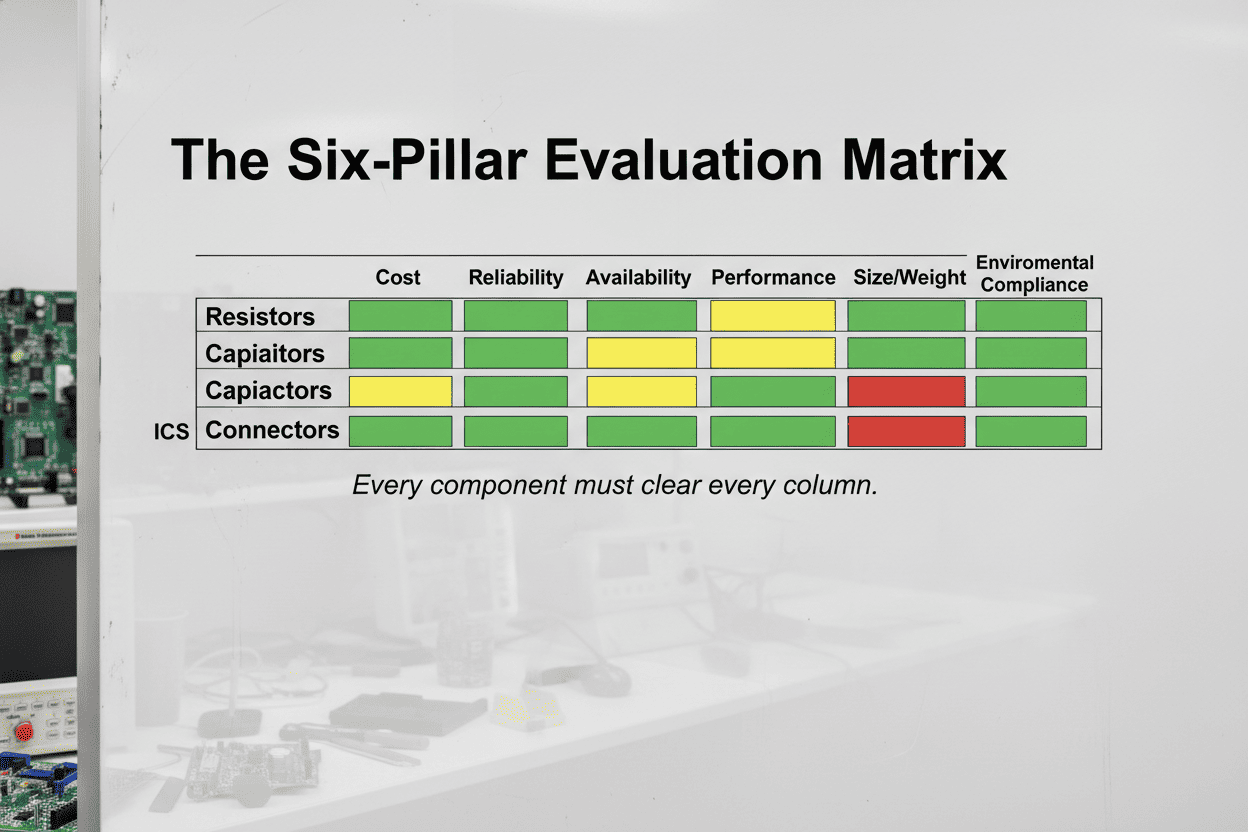
After safety classification, every component candidate must be evaluated against six interdependent criteria. Skipping any one of them is a fast track to a design review finding — or worse.
Pillar 1: Safety and Reliability
The non-negotiable foundation. For Class C components, every parameter on the datasheet deserves scrutiny:
- Operating parameters must stay below 50% of rated values across the full operating envelope (temperature, voltage, current)
- Triple-redundant architectures are standard for life-support equipment — three independent signal acquisition paths with voting logic
- MTBF targets must be established early: >50,000 hours for Class II monitoring devices, >100,000 hours for Class III life-support equipment, and 5-10 years of continuous in-vivo stability for implantables
A practical approach: maintain a reliability budget spreadsheet that tracks FIT (Failures In Time) rates for every Class B and C component. The total system FIT rate becomes a design input you can test against.
Pillar 2: Regulatory Compliance
This pillar answers two questions: "Is this component legal to use?" and "Can I prove it to an auditor?"
At minimum, every component must be RoHS and REACH compliant. But medical devices push further:
- Supplier ISO 13485 certification is strongly preferred — it means the supplier understands medical quality management
- Full supply chain traceability from wafer fab to your receiving dock, per FDA 21 CFR Part 11
- Material certificates, solder paste lot numbers, reflow profiles, AOI/X-ray inspection records — all audit-ready
Pro tip: Create a standard "Component Compliance Checklist" template. Every new component added to the BOM gets evaluated against it. Auditor walks in? Hand them the binder.
Pillar 3: Long-Term Availability and Obsolescence Management
This might be the most expensive oversight in medical device engineering. Consumer electronics turn over every 18 months. Medical devices stay on the market for 10-20 years. The component you pick today must be available — or have a validated replacement path — a decade from now.
The Tortai Technologies team describes it well: imagine your Class II medical device just received FDA 510(k) clearance, market launch is a success, and then an email lands in your inbox — your core microcontroller is going EOL in 12 months. Now you're looking at a design change submission, re-verification, potentially new clinical data... easily a $500K-$2M disruption.
Mitigation strategies:
- Prefer components with published longevity commitments (10+ years)
- Require PCN (Product Change Notification) agreements from suppliers
- Maintain a qualified alternate parts list for every single-source component
- Consider die-bank agreements for custom or niche ICs — pay the supplier to reserve wafers for your projected production life
- Use industry databases like SiliconExpert or IHS Markit to monitor lifecycle status
Pillar 4: Environmental Adaptability
Medical devices face environmental extremes most consumer products never encounter:
- Autoclave sterilization: 121°C at 103 kPa for 30 minutes. Insulation resistance must stay above 10¹² Ω post-cycle
- EtO sterilization: Requires ventilation design (0.1 mm diameter holes, 1 hole/cm²). Residual EtO must be ≤10 μg/g per ISO 10993-7
- Chemical exposure: 75% ethanol immersion for 24 hours should cause ≤0.5% weight change in PCB materials
- EMC environment: Radiated emissions must stay below 30 dBμV/m — far stricter than commercial electronics
For each sterilization method your device will encounter, add a dedicated column to your component selection matrix. Some capacitors degrade significantly under EtO. Some connectors warp in autoclave. You need to know before you commit.
Pillar 5: Biocompatibility (ISO 10993)
Every material that contacts the patient — housings, cables, coatings, adhesives — must pass the ISO 10993 gauntlet:
| Test | Standard | Acceptance Criteria |
|---|---|---|
| Cytotoxicity | ISO 10993-5 | Rating 0 (cell survival ≥ 90%) |
| Skin Irritation | ISO 10993-10 | No erythema or edema |
| Sensitization | ISO 10993-10 | Negative (GPMT) |
| Leachables | ISO 10993-12 | Metal ions ≤ 0.01 mg/L; organic extractables ≤ 0.1 mg/cm² |
| Systemic Toxicity | ISO 10993-11 | No significant biological reactions |
For implantables, this is even more demanding. Dupont Kapton HN/MT polyimide is a common choice — it achieves ISO 10993-5 cytotoxicity rating 0. Parylene C coating over ENIG-finished PCBs provides both biocompatibility and corrosion resistance for long-term in-vivo use.
Pillar 6: Low-Power Design
For portable, wearable, and implantable devices, this pillar dominates the conversation. Every microamp counts when you're designing for a battery that must last 5-10 years inside a human body.
- MCU selection: Compare active-mode and sleep-mode current draw. Look for devices with multiple low-power modes and fast wake-up times
- Sensor selection: MEMS sensors with integrated signal conditioning can dramatically reduce analog front-end power
- Wireless modules: BLE 5.0+ offers significant power improvements over earlier versions. Consider duty-cycling strategies early
- Power management ICs: High-efficiency buck-boost converters (>90%) with ultra-low quiescent current are worth the premium
Pro tip: Build a power budget spreadsheet early in architecture phase. It forces you to account for every component's contribution and often reveals surprising power hogs.
PCB Materials: The Foundation Beneath Every Component
Your components are only as reliable as the board they're soldered to. Medical-grade PCBs demand materials decisions that go well beyond "FR-4, 1.6 mm, green solder mask."
Material Selection by Application
| Application | Recommended Material | Key Properties |
|---|---|---|
| General Medical | High-Tg FR-4 (≥170°C) | Withstands high-temperature sterilization; cost-effective |
| Implantables | Dupont Kapton HN / MT Polyimide | ISO 10993-5 cytotoxicity rating 0; biocompatible; flexible |
| High-Frequency / RF | Rogers RO4835™, RO4350B-M | Df = 0.0037, Tg > 280°C, sterilization-tolerant |
| Surgical Instruments | Rogers RO4350B-M | 134°C autoclave resistant; DFM sterility score 98/100 |
Cleanliness and Contamination Control
Medical PCBs must meet cleanliness standards far beyond commercial electronics:
- Ion contamination: ≤ 1.56 μg/cm² (per IPC-5704)
- Particle residue: ≤ 50 particles/cm² (≥ 5 μm)
- Implantables: ≤ 1 CFU/cm² (sterile requirement)
- Manufacturing environment: Class 10,000 (ISO 14644-1 Class 8) cleanroom minimum
- Cleaning process: 18.2 MΩ·cm ultrapure water + ultrasonic (60 kHz) + vacuum drying
Solder and Surface Finishes
- Use SnAg3.0Cu0.5 medical-grade solder (Pb ≤ 5 ppm); for implantables, consider Indium 100IN (Pb ≤ 10 ppm)
- ENIG finish (Ni 3-5 μm, Au 0.05-0.1 μm) provides 0.2 dB lower loss at 10 GHz and 10+ year shelf life
- Implantables: ENIG + parylene C biocompatible coating
Creepage, Clearance, and EMC: When Physics Meets Regulation
IEC 60601-1 imposes spacing requirements that surprise engineers coming from consumer electronics:
- Defibrillator circuits require ≥ 8 mm creepage between high-voltage and low-voltage circuits — roughly 4× standard industrial requirements
- General rule: Conservative spacing per IEC 60601-1 for the device's working voltage and pollution degree (typically Pollution Degree 2 for hospital environments)
EMC: The Silent Design Killer
Medical device EMC is not optional. IEC 60601-1-2 Ed. 4.1 imposes:
- Radiated emissions < 30 dBμV/m — tighter than FCC Part 15 Class B
- Immunity requirements covering ESD, radiated RF, conducted RF, electrical fast transients, surges, and magnetic fields
PCB-level strategies:
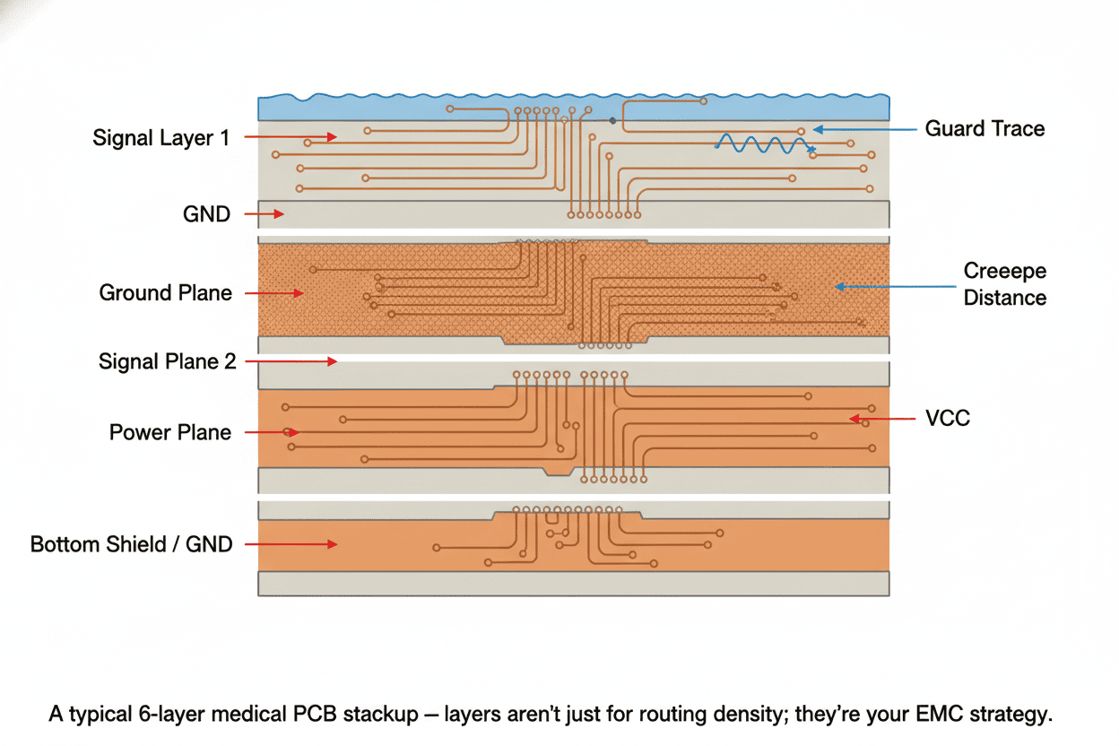
- Use dedicated ground and power planes (6+ layers is common for mixed-signal medical boards)
- Shield sensitive analog signals with guard traces (0.2 mm spacing)
- Route differential pairs for all analog sensor signals
- Never route over ground plane splits — this creates return path discontinuities that corrupt sensor readings
- Plan component placement so noisy digital sections are physically separated from sensitive analog front-ends
Derating: The Engineer's Safety Margin
Derating is the practice of operating components well below their rated maximums. In medical electronics, it's non-negotiable for Class B and C components.
Rule of thumb for Class C: Every operating parameter stays below 50% of the rated value.
This means:
- A capacitor rated for 25V operates at no more than 12.5V in your circuit
- A resistor rated for 0.25W dissipates no more than 0.125W
- An MCU rated for 85°C ambient sees no more than 42.5°C in worst-case thermal simulation
The IEEE/VITA 2818-2024 standard provides the latest formalized derating methodology. It's worth referencing in your design history file — it shows auditors you're following an industry-recognized approach, not just a rule of thumb.
The BOM Lifecycle: From Selection to End-of-Life
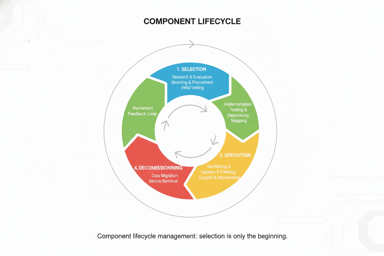
Component selection doesn't end when the BOM is released. In medical devices, it's a continuous activity.
Phase 1: Selection (Design Input)
- Apply the six-pillar evaluation
- Document every decision in the design history file
- Identify single-source risks
Phase 2: Qualification (Design Verification)
- Electrical characterization across temperature
- Accelerated life testing for Class C components
- Biocompatibility testing as needed
Phase 3: Production (Design Transfer)
- Incoming inspection per AQL sampling plans
- Supplier audit schedule
- PCN monitoring
Phase 4: Sustaining (Post-Market)
- Periodic lifecycle status review (quarterly minimum)
- Alternate part validation
- End-of-life mitigation planning
Common Mistakes That Trigger Audits, Recalls, and Redesigns
Drawing from published FDA recall data, industry postmortems, and the collective experience of medical hardware teams, here are the mistakes that keep showing up:
1. Trusting the Datasheet Alone
Datasheets present typical performance at 25°C. Your device operates at 5°C in an ambulance bay and 50°C in a sterilization cycle. Always characterize components across your actual operating envelope.
2. Ignoring Single-Source Risk
That amazing analog front-end IC from a single niche supplier? It's your biggest liability. If you can't find a pin-compatible alternate, budget for a die-bank or a redesign.
3. Skipping EMC Pre-Compliance
Waiting until formal EMC testing to discover radiated emissions problems is a schedule-killer. Budget for pre-compliance scans at every prototype iteration.
4. Designing for "Typical" Sterilization Cycles
Your device might see 100 autoclave cycles in its lifetime. Test to 200. Margin is not optional in medical devices.
5. Neglecting the PCB as a Component
The PCB is a component too. Substrate material, surface finish, and cleanliness directly impact reliability. A well-selected IC on a poorly specified board is still a failing device.
6. Underestimating Documentation Burden
Every component decision needs a documented rationale tied to a requirement. "Engineering judgment" alone won't satisfy an FDA auditor. Write it down.
The 2026 Checklist: A Practical Selection Workflow
Here's a step-by-step workflow you can adapt to your QMS:
- Safety-classify every component (Class A/B/C per ISO 14971)
- Apply the six-pillar evaluation to every Class B and C candidate
- Derate Class C components to ≤ 50% of rated limits
- Check lifecycle status (SiliconExpert, IHS, or equivalent) — flag anything with < 5 years projected availability
- Document the rationale — link each selection to a design input requirement
- Pre-compliance EMC scan at first prototype — don't wait for formal testing
- Peer review the BOM — have another engineer challenge every single-source component
- Establish PCN monitoring — subscribe to supplier change notifications
- Schedule quarterly lifecycle reviews — don't let obsolescence surprise you
- Plan for sterilization — if your device will be sterilized, add a dedicated column to your selection matrix
Frequently Asked Questions
Q: What's the difference between "medical-grade" and "industrial-grade" components?
Medical-grade isn't a formal component classification like AEC-Q100 is for automotive. Instead, it means the component has been selected, qualified, and documented according to a medical QMS (ISO 13485), with full traceability, and evaluated against the specific safety and reliability requirements of the intended device class. Some manufacturers do offer "medical" product lines with enhanced screening and longer lifecycle commitments — but always verify, don't assume.
Q: Can I use commercial off-the-shelf (COTS) components in a Class II medical device?
Yes, for Class A and some Class B functions. But you must justify the decision through risk analysis (ISO 14971), and you accept the burden of proving reliability and managing obsolescence without the supplier's help. For Class C functions, COTS components demand significantly more qualification testing.
Q: How do I handle a component going EOL mid-production?
This is why alternate part strategies exist. If you have a qualified alternate, you can transition with a relatively lightweight change notification. If you don't, you're looking at a redesign, re-verification, and potentially a new 510(k) submission — plan 12-18 months and significant cost. Die-bank agreements are expensive but cheaper than a forced redesign.
Q: What's the single most overlooked aspect of medical component selection?
Obsolescence management. Most engineers focus on electrical performance and regulatory compliance during design, but the biggest headaches come 5-8 years later when critical components disappear from the market. Start lifecycle monitoring on day one.
Q: Does the new AFNOR SPEC 2311 apply to my non-implantable device?
Directly, no — it's specific to Active Implantable Medical Devices. But its qualification methodology and test protocols represent the state of the art for high-reliability component selection and may be referenced by auditors as a benchmark even for non-AIMD devices.
Key Takeaways
Component selection for medical devices is a systems engineering discipline, not a procurement task. The engineers who do it well share a few habits:
- They treat every Class C component selection as a safety-critical design decision
- They maintain BOMs that include lifecycle status, not just part numbers
- They design for 20-year product lifetimes, not 18-month consumer cycles
- They document every decision as if an FDA auditor will read it tomorrow
- They stay current on the evolving standards landscape — AFNOR SPEC 2311 and IEC 60601-1 4th Edition are changing the game right now
