


MEMS Technology Selection Guide: Choosing the Right Micro-Electro-Mechanical Systems for Your Application
Target Audience: Electronics engineers, R&D team leads, product designers, procurement managers, and technical decision-makers working with sensor integration, IoT devices, automotive systems, and consumer electronics.
Table of Contents
- Introduction: Understanding MEMS in Modern Semiconductor Technology
- Key Technical Parameters of MEMS Devices
- MEMS Types and Application-Specific Selection
- Performance Comparison: MEMS vs Traditional Sensors
- Design Considerations and Common Implementation Pitfalls
- Supply Chain and Sourcing Considerations
- FAQ
- Conclusion and Next Steps
1. Introduction: Understanding MEMS in Modern Semiconductor Technology
Micro-electro-mechanical systems (MEMS) represent a critical intersection of mechanical engineering and semiconductor technology, integrating microscopic mechanical structures with electronic circuits on a single silicon substrate. Unlike traditional discrete sensors, MEMS devices leverage semiconductor fabrication processes—including surface micromachining, bulk micromachining, and wafer bonding—to create miniaturized sensors and actuators with unprecedented performance-to-size ratios.
The global MEMS market has grown substantially across automotive, industrial, consumer electronics, and medical applications. Engineers face increasing pressure to select MEMS components that balance sensitivity, power consumption, package size, and cost while meeting stringent reliability requirements. This guide provides practical selection criteria based on real-world design constraints and helps you avoid common specification misinterpretations that can lead to costly redesigns.
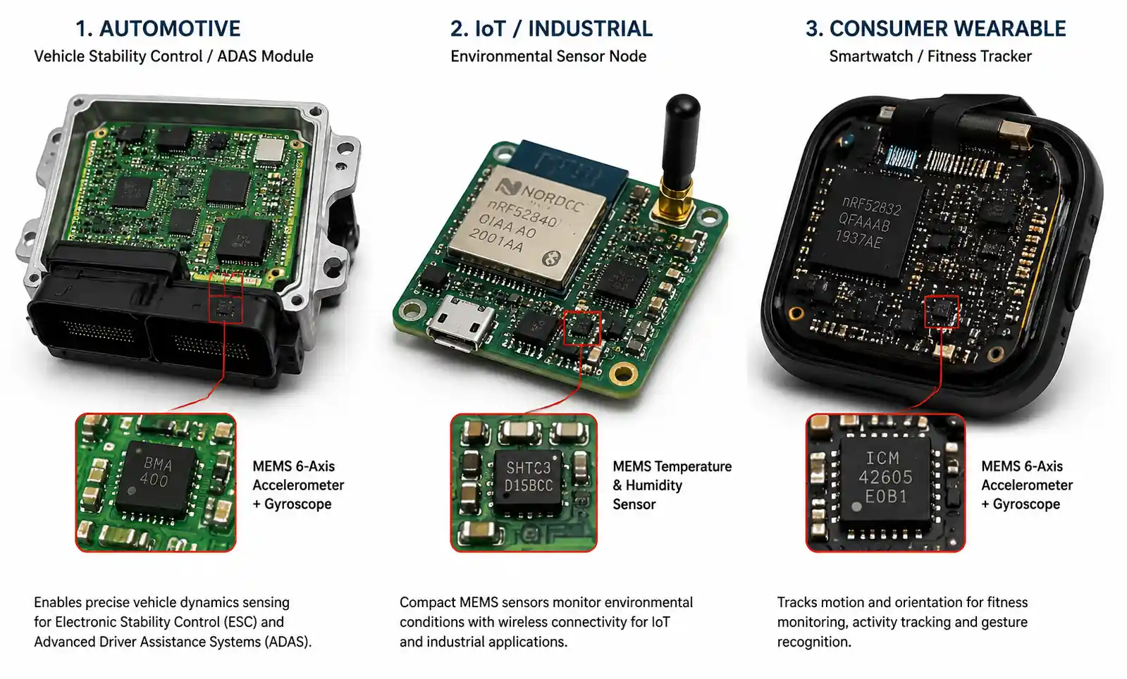
Whether you're designing an IoT sensor node requiring ultra-low power consumption, an automotive safety system demanding AEC-Q qualification, or a consumer wearable prioritizing compact packaging, understanding the trade-offs between different MEMS technologies is essential for optimal component selection.
2. Key Technical Parameters of MEMS Devices
When evaluating MEMS components for your design, several technical parameters directly impact system performance. Understanding these specifications and their engineering implications is critical for proper selection.
2.1 Sensitivity and Measurement Range
MEMS sensitivity defines the output signal change per unit of measured physical quantity. For accelerometers, this is typically expressed in mV/g or LSB/g for digital outputs. Higher sensitivity improves signal-to-noise ratio but often reduces measurement range. A common design mistake is selecting maximum sensitivity without considering the expected acceleration range in your application—this can lead to sensor saturation during normal operation.
For pressure sensors, sensitivity is expressed in mV/kPa or mV/V/kPa, with full-scale output ranges typically from 10 mV to 100 mV for analog sensors. When selecting pressure MEMS for medical or industrial applications, verify that the sensitivity specification matches your ADC resolution requirements and accounts for temperature-induced drift.
2.2 Power Consumption and Operating Modes
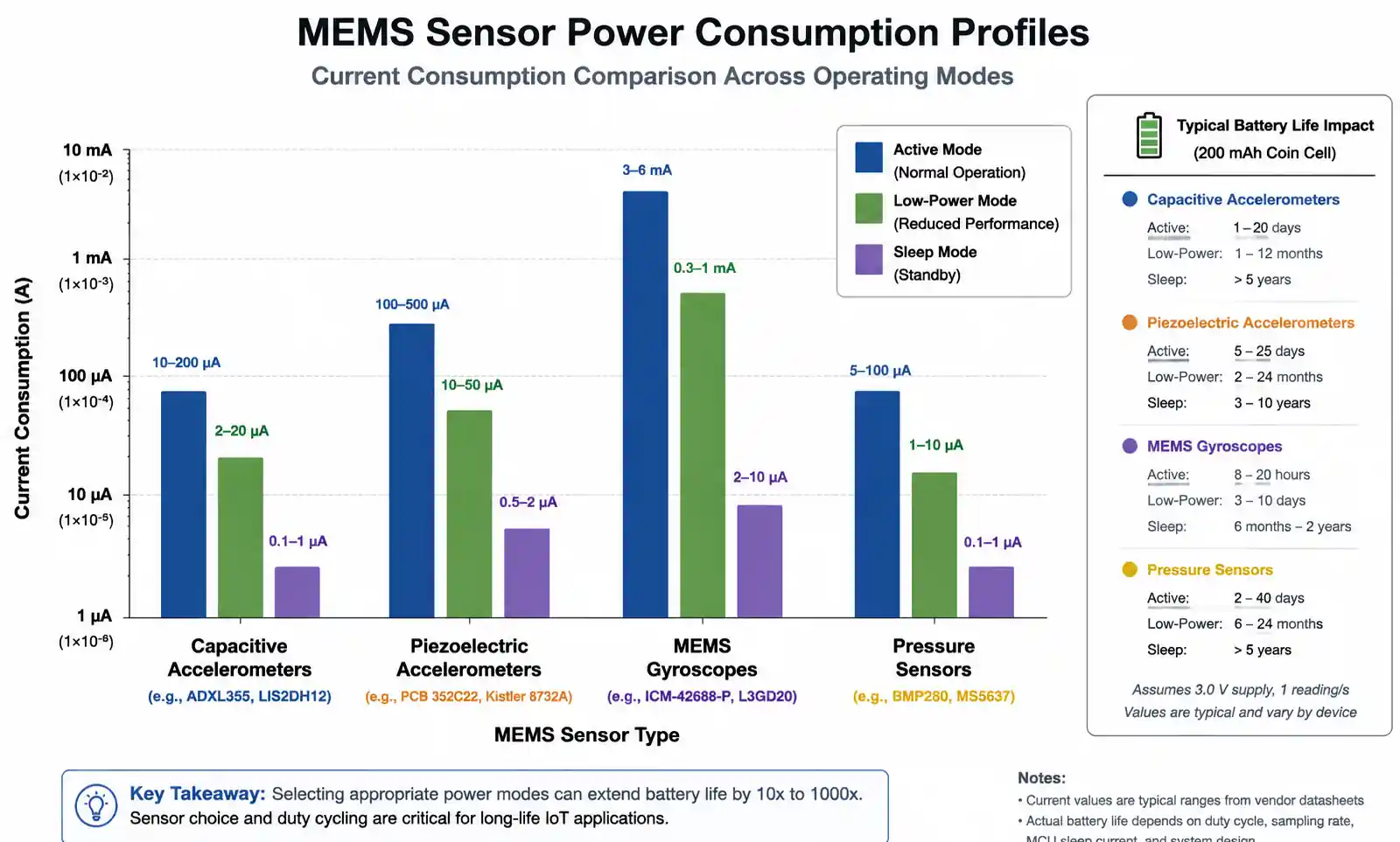
MEMS power consumption varies dramatically based on device architecture and operating mode. Capacitive MEMS accelerometers typically consume 10–200 μA in continuous mode, while piezoelectric designs may require 100–500 μA. For battery-powered IoT applications, pay close attention to sleep mode current (often 1–5 μA) and wake-up time, as duty-cycled operation significantly impacts total system power.
Gyroscopes generally consume more power than accelerometers due to their need for continuous mechanical oscillation. A typical MEMS gyroscope draws 3–6 mA during active measurement, making power management architecture critical in portable devices. Consider MEMS with integrated power management or low-power modes that can be synchronized with your MCU sleep cycles.
2.3 Noise Density and Resolution
Noise density, measured in μg/√Hz for accelerometers or °/s/√Hz for gyroscopes, determines the minimum detectable signal. Lower noise density enables higher resolution measurements but may come at the cost of increased power consumption or larger die size. For high-precision applications like inertial navigation or seismic monitoring, noise density below 25 μg/√Hz is typically required.
The relationship between noise density and bandwidth is critical—narrowing your measurement bandwidth through digital filtering can improve effective resolution. However, ensure your filter design doesn't introduce excessive phase lag if real-time response is important for your control loop or safety function.
3. MEMS Types and Application-Specific Selection
Different MEMS sensing technologies offer distinct advantages depending on your application requirements. This section provides selection guidance based on common design scenarios.
3.1 MEMS Accelerometers
| Parameter | Capacitive MEMS | Piezoelectric MEMS | Piezoresistive MEMS |
|---|---|---|---|
| Measurement Range | ±2g to ±16g (consumer) ±50g to ±200g (automotive) |
±50g to ±500g | ±2g to ±250g |
| Frequency Response | DC to 1 kHz | 1 Hz to 10 kHz+ | DC to 5 kHz |
| Power Consumption | 10–200 μA | 100–500 μA | 50–300 μA |
| Temperature Stability | Excellent | Good (requires compensation) | Moderate (high drift) |
| Best Applications | Tilt sensing, motion detection, consumer devices | Vibration monitoring, shock detection, crash sensors | Harsh environment, high-g applications |
| Typical Cost Range | $0.50–$3.00 | $2.00–$8.00 | $3.00–$12.00 |
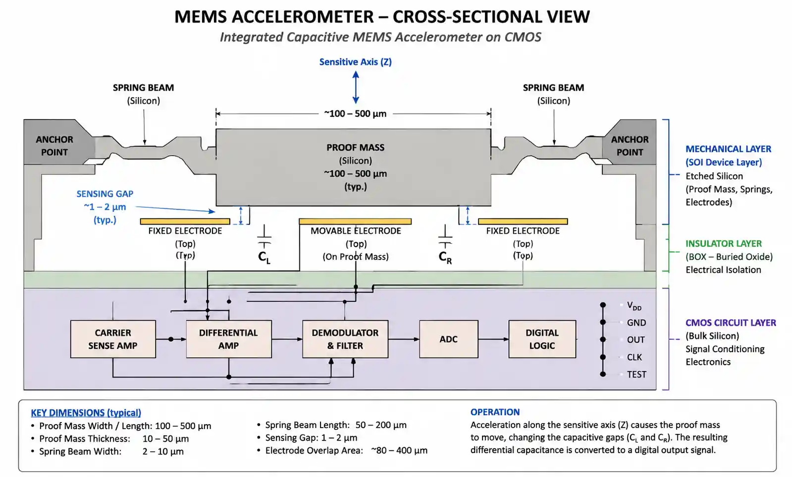
Capacitive MEMS accelerometers dominate consumer and mobile applications due to their excellent DC response, low power consumption, and cost-effectiveness. They measure acceleration by detecting capacitance changes in micro-machined proof masses suspended by spring structures. For smartphone orientation detection or fitness tracking, capacitive accelerometers with ±2g to ±8g range and 12–16 bit resolution are typically optimal.
Piezoelectric MEMS excel in high-frequency vibration monitoring applications such as predictive maintenance in industrial equipment or automotive knock detection. Their inability to measure DC signals (they're AC-coupled by nature) makes them unsuitable for tilt sensing but ideal for dynamic vibration analysis where frequencies above 1 Hz are of interest.
3.2 MEMS Gyroscopes
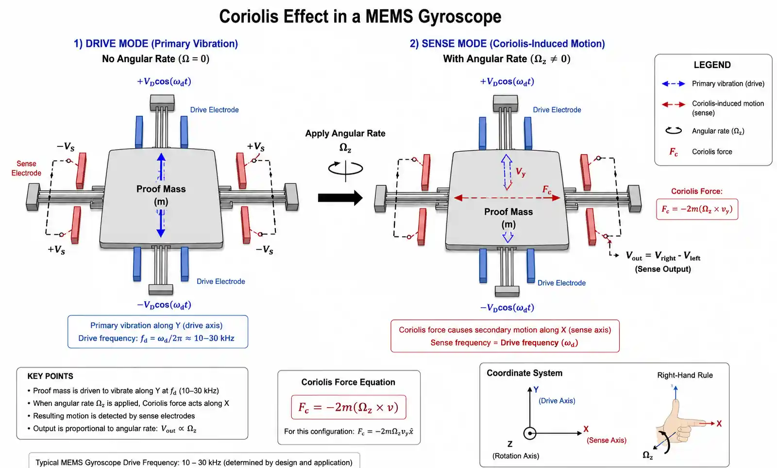
MEMS gyroscopes measure angular velocity using the Coriolis effect on vibrating microstructures. Selection depends primarily on your required accuracy, drift specifications, and power budget.
| Application Type | Range Requirement | Bias Stability Needed | Recommended Architecture |
|---|---|---|---|
| Consumer electronics (gaming, AR/VR) | ±250 to ±2000°/s | 10–50°/h | Single-axis or 3-axis consumer-grade |
| Drone stabilization | ±500 to ±2000°/s | 5–20°/h | Automotive-grade 3-axis with fast response |
| Automotive (ESC, ADAS) | ±300°/s | <10°/h, AEC-Q100 qualified | Automotive-grade with self-test |
| Industrial robotics | ±100 to ±500°/s | 1–5°/h | High-performance tactical-grade |
| Inertial navigation | ±100°/s | <0.1°/h | Tactical or navigation-grade (expensive) |
Bias stability (also called in-run bias stability) is often misunderstood but critically important for any application requiring angle estimation through integration. A gyroscope with 10°/h bias stability will accumulate 10 degrees of error per hour even when stationary—this drift must be compensated through sensor fusion with accelerometers or magnetometers.
3.3 MEMS Pressure Sensors
MEMS pressure sensors use piezoresistive or capacitive sensing elements on silicon diaphragms. Key selection factors include pressure range, media compatibility, and package type (absolute, gauge, or differential pressure).
For automotive manifold absolute pressure (MAP) sensors, a typical specification is 20–250 kPa measurement range with ±1% accuracy over -40°C to 125°C. Medical blood pressure monitoring requires higher accuracy (±0.5%) and biocompatibility certification. Industrial process control often demands stainless steel media isolation and 4–20 mA current loop outputs.
When selecting MEMS pressure sensors, verify that the specified accuracy includes temperature effects across your operating range—many datasheets list room temperature accuracy separately from temperature coefficient of offset (TCO) and temperature coefficient of sensitivity (TCS), which must be combined for total error budget analysis.
4. Performance Comparison: MEMS vs Traditional Sensors
Understanding when MEMS technology provides clear advantages over conventional sensing approaches helps optimize both performance and cost.
| Sensor Type | MEMS Advantage | Traditional Sensor Advantage | Crossover Point |
|---|---|---|---|
| Accelerometers | Size, power, cost, integration | High-g capability (>500g), extremely low frequency (<0.01 Hz) | Above ±200g or DC measurements |
| Gyroscopes | Size, cost, fast startup | Ultra-high precision (navigation-grade), very low drift | Bias stability <0.1°/h required |
| Pressure Sensors | Size, digital output, temperature compensation | Very high pressure (>10 bar), corrosive media | Extreme pressure or chemical exposure |
| Microphones | Flat frequency response, low power, SMD packaging | High sound pressure level (>130 dB SPL) | Professional audio recording |
| Oscillators | Shock resistance, low power, programmability | Ultra-low phase noise, extreme temperature stability | Telecom/RF applications requiring -140 dBc/Hz phase noise |
MEMS devices achieve dramatic size reduction through semiconductor batch fabrication—a MEMS accelerometer occupies less than 4 mm² compared to 100+ mm² for a conventional piezoelectric accelerometer. This integration advantage enables applications like truly wireless earbuds, where space constraints make traditional sensors impractical.
However, MEMS sensors typically cannot match the ultimate performance of larger, discrete sensors in extreme conditions. High-end seismic sensing still relies on force-balance accelerometers, and fiber-optic gyroscopes remain superior for navigation applications requiring <0.01°/h stability. The decision point comes down to whether your application's performance requirements fall within MEMS capabilities, which have continuously improved while costs have decreased.
5. Design Considerations and Common Implementation Pitfalls
Successful MEMS integration requires attention to PCB layout, power supply design, and proper understanding of sensor coordinate systems and output interfaces.
5.1 PCB Layout and Mechanical Mounting
MEMS sensors contain microscopic mechanical structures that can be affected by PCB stress and vibration coupling. Mount MEMS accelerometers and gyroscopes away from board edges and mounting holes, preferably near the board's mechanical neutral axis. Avoid placing them near large components that could create thermal gradients.
For highest accuracy, minimize the distance between the MEMS device and mounting reference point. In applications measuring rotational motion, each millimeter of offset introduces tangential acceleration that contaminates your gyroscope measurement. Document the exact sensor location for your mechanical engineers to properly calculate coordinate transformations.
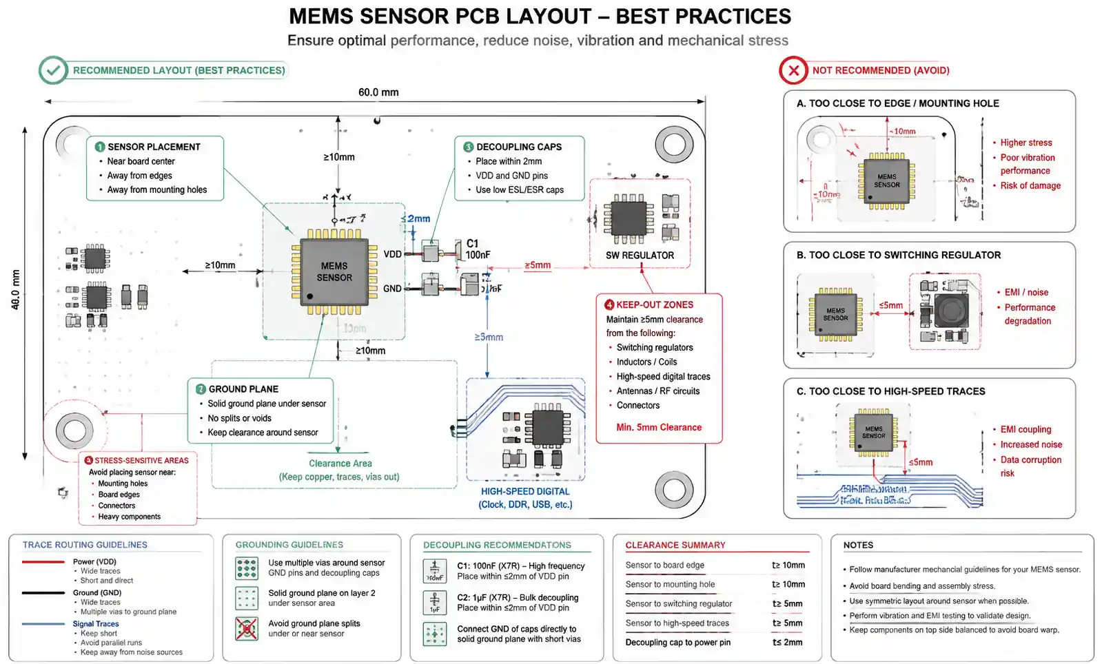
A critical mistake is routing high-speed digital signals or switching power supplies near MEMS analog outputs. Even with differential interfaces, electromagnetic interference can couple into the sensitive proof mass structures. Use ground planes and maintain at least 5 mm clearance from noise sources. For SPI or I²C digital interfaces, proper termination and bypass capacitors per datasheet specifications are essential to prevent communication errors.
5.2 Power Supply Filtering and Decoupling
MEMS devices require clean, stable power supplies—typically 1.8V to 3.3V with <50 mV ripple. Place decoupling capacitors as close as possible to the VDDIO and VDD pins, using a combination of 100 nF ceramic (X7R or X5R) and 10 μF bulk capacitors. The ceramic capacitor should be within 2 mm of the power pin to effectively suppress high-frequency noise.
Some MEMS accelerometers and gyroscopes include internal voltage regulators, but external supply noise can still couple through substrate effects. For precision applications, consider using a dedicated low-dropout regulator (LDO) with <40 μVrms output noise rather than sharing the main system supply. This becomes critical when the MEMS shares a board with RF transmitters, DC-DC converters, or motor drivers.
5.3 Calibration and Sensor Fusion
Out-of-box MEMS sensors typically have ±3% sensitivity tolerance and ±50 mg (for accelerometers) or ±3°/s (for gyroscopes) offset errors. For applications requiring better accuracy, implement factory or field calibration. Multi-point calibration across temperature improves accuracy to ±1% or better.
Gyroscope drift integration quickly accumulates angle errors without correction. Complementary filters or Kalman filters that fuse accelerometer gravity references with gyroscope measurements are essential for orientation tracking. Be aware that accelerometer measurements include both gravity and linear acceleration—your fusion algorithm must distinguish between tilt and true linear motion.
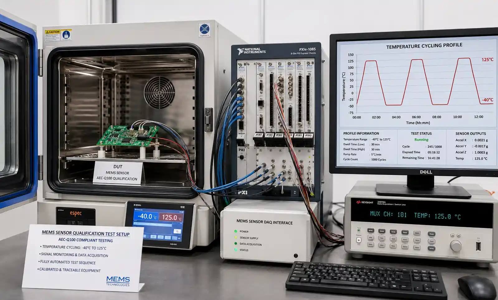
5.4 Environmental Stress Testing
MEMS reliability strongly depends on proper environmental qualification. For automotive applications, devices must meet AEC-Q100 standards including high-temperature operating life (HTOL), temperature cycling, and mechanical shock tests. Consumer-grade MEMS may not survive automotive thermal cycling from -40°C to 125°C or the mechanical shock profiles typical in automotive crashes.
Humidity can affect MEMS performance, particularly for devices with acoustic ports (pressure sensors, microphones). Conformal coating of the PCB is recommended, but avoid covering the MEMS port opening. Some pressure sensors include gel protection over the sensing diaphragm for media isolation—verify this is appropriate for your measured fluid.
6. Supply Chain and Sourcing Considerations
MEMS devices are manufactured by a relatively small number of suppliers using specialized fabrication processes, making supply chain management important for long product lifecycles.
6.1 Major MEMS Suppliers and Lead Times
| Supplier | Key Product Lines | Typical Lead Time | Minimum Order Quantity | Key Certifications |
|---|---|---|---|---|
| Bosch Sensortec | Accelerometers, gyroscopes, pressure sensors, environmental sensors | 12–16 weeks | 3,000–5,000 pieces | AEC-Q100, IATF 16949 |
| STMicroelectronics | IMUs, accelerometers, gyroscopes, MEMS microphones | 14–20 weeks | 5,000–10,000 pieces | AEC-Q100, ISO 26262 |
| InvenSense (TDK) | High-performance IMUs, gyroscopes, pressure sensors | 12–18 weeks | 2,500–7,500 pieces | AEC-Q100 |
| Analog Devices | Precision MEMS accelerometers, gyroscopes | 16–24 weeks | 1,000–3,000 pieces (depending on grade) | AEC-Q100, aerospace-qualified |
| Infineon | MEMS microphones, pressure sensors | 12–16 weeks | 5,000 pieces | Automotive-qualified |
Lead times have extended significantly in recent years due to capacity constraints in MEMS foundries and increased automotive demand. For high-volume production, engage suppliers early in the design phase and consider long-term supply agreements. Many MEMS manufacturers offer engineering samples with shorter lead times for prototyping, but transition to production orders requires planning 6–9 months ahead.
6.2 Handling Obsolescence and Second-Sourcing
MEMS products typically have 7–10 year lifecycles, shorter than many industrial or automotive applications require. Monitor product change notifications (PCNs) and end-of-life (EOL) announcements closely. When a MEMS sensor approaches EOL, migration to a newer generation often requires firmware changes due to different sensitivity specifications, communication protocols, or package pinouts.
True second-sourcing for MEMS is challenging because each manufacturer's device has unique characteristics. Even "compatible" parts from different suppliers require calibration updates and validation testing. For critical applications, negotiate last-time-buy quantities or consider pin-compatible alternatives identified during the initial design phase.
Work with authorized distributors like Digi-Key, Mouser, or Arrow who provide real-time inventory visibility and traceability to avoid counterfeit components. Counterfeit MEMS sensors, while less common than for ICs, do exist in the market—particularly for high-value automotive or industrial-grade devices.
7. FAQ
What is the difference between MEMS and traditional semiconductor sensors?
MEMS devices integrate mechanical structures (like suspended masses, diaphragms, or resonating beams) with electronic circuits on a single silicon chip using semiconductor fabrication techniques. Traditional semiconductor sensors, such as Hall-effect sensors or photodiodes, rely purely on electronic properties without mechanical structures. This mechanical-electrical integration allows MEMS to measure physical quantities like acceleration, pressure, or rotation with excellent size, power, and cost advantages compared to discrete mechanical sensors.
How do I choose between analog and digital output MEMS sensors?
Analog MEMS sensors provide voltage or current outputs proportional to the measured quantity, requiring an external ADC and offering maximum flexibility in signal processing. Choose analog outputs when you need custom filtering, very high sampling rates (>10 kHz), or when integrating with existing analog signal chains. Digital MEMS sensors (SPI, I²C) include integrated ADCs, temperature compensation, and self-test features, simplifying system design and reducing component count. Digital interfaces are preferred for most modern designs unless sampling rate or customization requirements dictate analog.
What AEC-Q100 grade do I need for automotive MEMS applications?
AEC-Q100 qualification defines automotive temperature grades: Grade 0 (-40°C to 150°C) for engine compartment, Grade 1 (-40°C to 125°C) for general automotive, Grade 2 (-40°C to 105°C) for passenger compartment, and Grade 3 (-40°C to 85°C) for non-critical systems. Most automotive MEMS sensors are Grade 1 qualified. For safety-critical ADAS or ESC applications, also verify ISO 26262 functional safety compliance (typically ASIL B or C) beyond basic AEC-Q100 qualification.
How does temperature affect MEMS sensor accuracy?
Temperature influences MEMS sensors through multiple mechanisms: thermal expansion changes mechanical structure dimensions, affecting sensitivity; temperature-dependent material properties alter electrical characteristics, creating offset drift; and packaging stress varies with temperature. Specify total error budget including temperature coefficient of offset (TCO) and temperature coefficient of sensitivity (TCS) across your full operating range. High-quality MEMS include internal temperature compensation, but residual errors of 0.01%/°C (sensitivity) and 1 mg/°C or 0.01°/s/°C (offset) are typical even after compensation.
Can MEMS sensors survive mechanical shock during shipping and handling?
Most MEMS sensors are rated for mechanical shock in the range of 3,000–10,000g for <1 ms duration when unpowered, which covers normal shipping and drop scenarios. However, powered operation typically reduces shock tolerance to 1,500–2,000g because internal circuitry must remain functional. Always follow manufacturer recommendations for mechanical stops and mounting to prevent proof mass damage. For extreme shock environments (automotive crash, military applications), specify devices explicitly qualified for high-g survival, and implement proper PCB mounting with vibration isolation if necessary.
What causes MEMS gyroscope drift and how can I minimize it?
MEMS gyroscope drift (bias instability) results from multiple sources: electronic noise in readout circuits, mechanical-thermal noise in the resonating structure, and temperature-dependent effects in the Coriolis sensing mechanism. Minimize drift by: (1) maintaining stable operating temperature through thermal management, (2) implementing runtime bias estimation using zero-velocity updates or stationary periods, (3) fusing gyroscope data with accelerometer and magnetometer inputs via Kalman filtering, and (4) selecting automotive or tactical-grade gyroscopes with <5°/h bias stability for applications requiring accurate angle tracking. Factory calibration across temperature further improves performance.
Are there standard footprints for MEMS sensors to enable second-sourcing?
Unlike some passive components, MEMS sensors do not have truly standardized footprints across manufacturers. However, common package types exist: LGA (land grid array) packages like 3x3x1 mm or 2.5x3x0.9 mm are widely used, and some suppliers offer "industry-standard pinouts" designed for compatibility. Nevertheless, second-sourcing typically requires PCB redesign or adapter circuits because even mechanically compatible packages may have different pin assignments, communication protocols, or mounting axis orientations. Design your layout with potential footprint variations in mind if second-sourcing is critical.
What testing is required to validate MEMS sensor selection for my application?
Validation testing should include: (1) functional testing across full operating temperature range to verify accuracy specifications, (2) power consumption measurement in all operating modes to confirm battery life calculations, (3) mechanical shock and vibration testing per your application's environmental profile, (4) electromagnetic compatibility (EMC) testing to ensure sensor outputs aren't corrupted by system noise, (5) long-term drift characterization if accuracy over time is critical, and (6) axis-alignment verification to ensure sensor coordinate system matches your mechanical reference frame. For safety-critical systems, additional functional safety validation per ISO 26262 or IEC 61508 is required.
8. Conclusion and Next Steps
MEMS technology has fundamentally transformed sensor integration in modern electronic systems, offering unprecedented combinations of small size, low power consumption, and cost-effectiveness that enable innovations across automotive, industrial, IoT, and consumer applications. Successful MEMS selection requires balancing multiple technical parameters—sensitivity vs. range, power vs. performance, accuracy vs. cost—while considering long-term supply chain stability and environmental qualification requirements.
When selecting MEMS components for your design, prioritize these key considerations: first, clearly define your application's measurement range, accuracy, and bandwidth requirements to avoid over-specifying expensive high-performance sensors or under-specifying and requiring costly redesigns. Second, carefully evaluate temperature effects and ensure specified accuracy includes your full operating temperature range. Third, plan your PCB layout and power supply architecture early to minimize noise coupling and mechanical stress effects. Finally, engage with suppliers during the design phase to secure long-term availability and understand lead times for production volumes.
For applications requiring high precision, low drift, or harsh environment operation, invest in proper calibration procedures and sensor fusion algorithms—these software approaches often deliver better overall system performance than simply selecting the highest-grade MEMS device. For automotive or safety-critical systems, verify both AEC-Q qualification and functional safety compliance (ISO 26262 or equivalent) before finalizing your design.
Recommended next steps:
- Download detailed datasheets for candidate MEMS sensors matching your application requirements
- Request evaluation boards or development kits to validate performance in your actual system environment before committing to high-volume orders
- Consult with your supplier's field application engineers (FAE) for design reviews, particularly for first-time MEMS integration projects
- Use online parametric selection tools from major manufacturers to quickly filter options by key specifications
- If designing for long product lifecycles (>5 years), establish direct communication with MEMS suppliers regarding product roadmaps and EOL planning
The MEMS market continues to evolve rapidly, with ongoing improvements in noise performance, power consumption, and integration density. Staying informed about new device releases and manufacturing capabilities will help you optimize your designs for both current production and future product generations.