


Molded Case Circuit Breaker (MCCB): Engineering Principles, Design, and Industrial Applications
Molded Case Circuit Breakers (MCCBs) are essential protection devices in low-voltage power distribution systems. This article provides an engineering-level analysis of MCCBs, focusing on their operating principles, internal design, trip characteristics, selection methodology, and real-world applications. It is structured to support practical decision-making in industrial and commercial electrical systems while maintaining SEO clarity and technical depth.
Table of Contents
- 1. Overview of MCCB
- 2. Working Principle of MCCB
- 3. Internal Components and Design Details
- 4. Trip Characteristics and Protection Curves
- 5. Types of MCCBs
- 6. Ratings and Selection Criteria
- 7. MCCB vs MCB: Engineering Comparison
- 8. Industrial Applications
- 9. Common Failure Modes and Troubleshooting
- 10. Future Trends in MCCB Technology
- 11. FAQ
1. Overview of MCCB
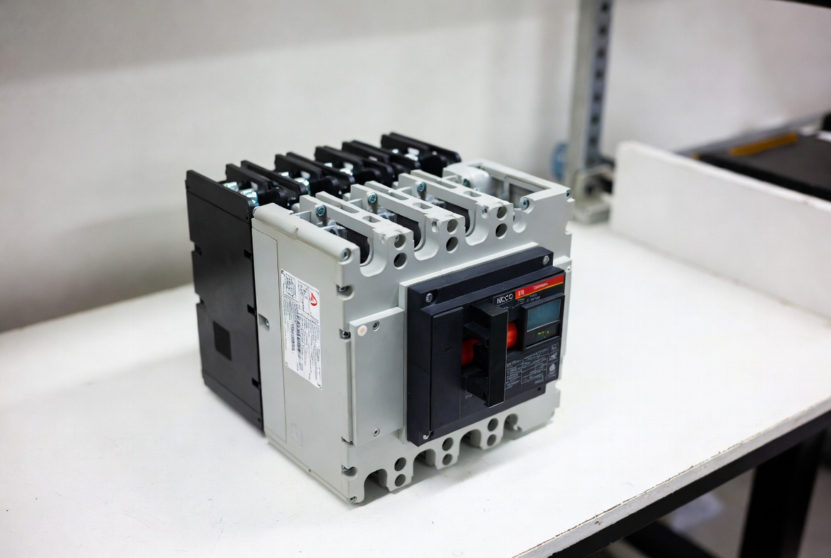
A Molded Case Circuit Breaker (MCCB) is a low-voltage protective device designed to interrupt fault currents such as overloads and short circuits. It is enclosed in a molded insulating housing and provides:
- High current handling capability (up to 2500A+)
- Adjustable protection settings
- High breaking capacity (Icu)
- Reusability after fault clearance
MCCBs are widely used in industrial plants, commercial buildings, and power distribution networks.
2. Working Principle of MCCB
An MCCB operates using a combination of thermal and magnetic protection mechanisms, ensuring both delayed and instantaneous fault response.
2.1 Normal Operation
Under normal conditions:
- Current flows through closed contacts
- The breaker remains in ON state
- Minimal resistance ensures efficient conduction
2.2 Overload Protection (Thermal Mechanism)
- A bimetallic strip heats up due to excessive current
- Thermal expansion causes it to bend
- This triggers a delayed trip (inverse time characteristic)
This delay allows temporary inrush currents (e.g., motor startup) without unnecessary interruption.
2.3 Short Circuit Protection (Magnetic Mechanism)
- Fault current generates a strong magnetic field
- An electromagnetic coil activates instantly
- The breaker trips within milliseconds
2.4 Arc Extinction
When contacts separate:
- An electric arc forms
- Arc chutes split and cool the arc
- The arc is extinguished safely, preventing damage
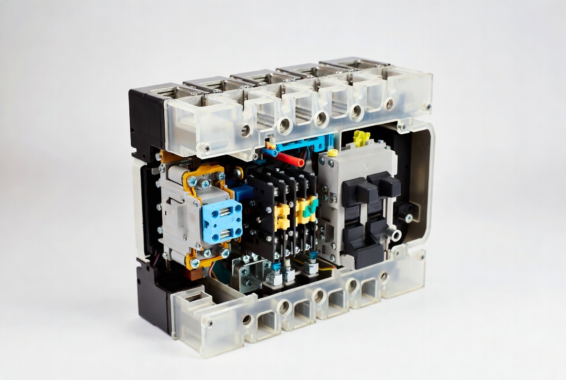
3. Internal Components and Design Details
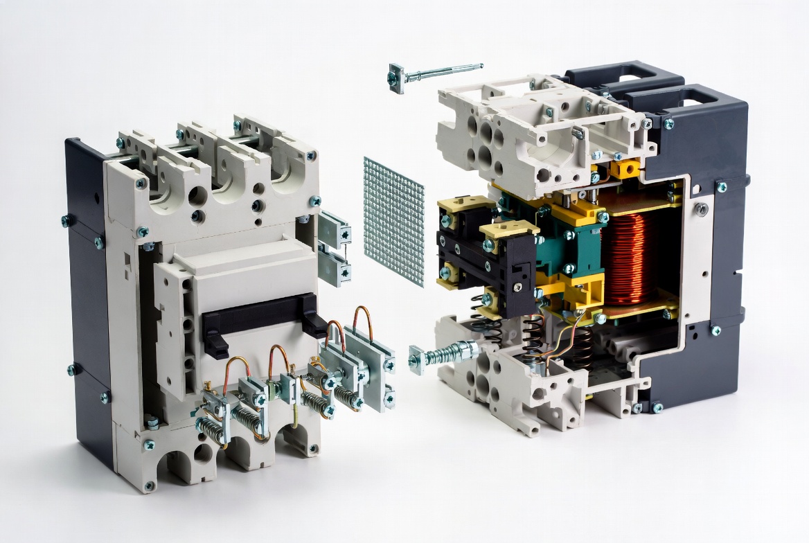
3.1 Contact System
- Made of silver alloy (AgSnO₂)
- Designed for:
- Low resistance
- High arc erosion resistance
- Fast separation
3.2 Trip Unit
Two main types:
- Thermal-magnetic (traditional)
- Electronic (advanced)
Electronic trip units provide:
- Adjustable protection curves
- High precision fault detection
- Communication capability
3.3 Operating Mechanism
- Spring-loaded mechanism ensures rapid disconnection
- Independent of manual operation speed
3.4 Molded Case Housing
- Thermoset insulating material
- Provides:
- Electrical insulation
- Mechanical protection
- Heat resistance
4. Trip Characteristics and Protection Curves
4.1 Time-Current Characteristics (TCC)
MCCBs follow an inverse-time curve:
- Higher current → faster trip
- Lower overload → slower response
4.2 Selectivity (Coordination)
In multi-level systems:
- Downstream breakers trip first
- Upstream breakers act as backup
This ensures system stability and minimizes outages.
5. Types of MCCBs
5.1 Thermal-Magnetic MCCB
- Most common type
- Cost-effective and reliable
5.2 Magnetic-Only MCCB
- Instantaneous protection only
- Used with external overload relays
5.3 Electronic MCCB
- Microprocessor-based
- High accuracy and programmability
- Suitable for critical systems
5.4 Adjustable MCCB
- Allows tuning of:
- Current threshold
- Time delay
- Trip curves
6. Ratings and Selection Criteria
6.1 Key Parameters
| Parameter | Description |
|---|---|
| In | Rated current |
| Icu | Ultimate breaking capacity |
| Ics | Service breaking capacity |
| Ui | Insulation voltage |
| Ue | Operational voltage |
6.2 Selection Methodology
Step-by-step:
- Calculate load current
- Determine fault current level
- Select MCCB such that:
- In ≥ 1.25 × load current
- Icu ≥ fault current
- Verify coordination with upstream/downstream devices
7. MCCB vs MCB: Engineering Comparison
| Feature | MCCB | MCB |
|---|---|---|
| Current Range | Up to 2500A+ | Up to 100A |
| Breaking Capacity | High | Low |
| Adjustability | Yes | No |
| Application | Industrial | Residential |
| Size | Larger | Compact |
Conclusion: MCCBs are designed for heavy-duty and flexible protection, while MCBs are intended for simple, low-current circuits.
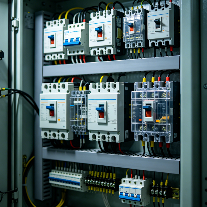
8. Industrial Applications
8.1 Power Distribution Systems
- Main and feeder protection
- Load management
8.2 Motor Protection
- Handles high inrush currents
- Prevents overload damage
8.3 Renewable Energy Systems
- Solar inverters
- Battery storage protection
8.4 Commercial Infrastructure
- HVAC systems
- Elevators
- Lighting systems
9. Common Failure Modes and Troubleshooting
9.1 Frequent Tripping
Causes:
- Overload
- Inrush current
- Harmonics
Solution:
- Adjust trip settings
- Verify load conditions
9.2 Overheating
Causes:
- Loose terminals
- High contact resistance
Solution:
- Tighten connections
- Inspect conductors
9.3 Failure to Trip
Causes:
- Faulty trip unit
- Mechanical failure
Action: Immediate replacement required
10. Future Trends in MCCB Technology
10.1 Smart MCCBs
- IoT-enabled monitoring
- Remote control and diagnostics
10.2 Digital Protection
- Adaptive trip curves
- Data-driven fault analysis
10.3 Compact Modular Design
- Space-saving installations
- Easy maintenance
10.4 Communication Integration
- Modbus / Ethernet support
- Integration with SCADA systems
11. FAQ
Q1: Why use MCCB instead of a fuse?
A: MCCBs are reusable, adjustable, and provide more precise protection compared to fuses.
Q2: What is the difference between Icu and Ics?
A:
- Icu: Maximum breaking capacity
- Ics: Operational breaking capacity after repeated use
Q3: How to avoid nuisance tripping?
A:
- Adjust instantaneous settings
- Consider motor starting current
- Use delay features
Q4: Can MCCBs be used in DC systems?
A: Yes, but only DC-rated MCCBs should be used due to arc characteristics.
Q5: When should I choose an electronic MCCB?
A: For high-reliability systems such as data centers, smart grids, and industrial automation.
Conclusion
MCCBs are not just protective devices but critical components in modern electrical system design. Their ability to provide adjustable, high-capacity, and reliable protection makes them indispensable in industrial environments. With the integration of digital and smart technologies, MCCBs are evolving into intelligent protection nodes within advanced power systems.