


Op-Amp Slew Rate: A Complete Selection and Design Guide for High-Performance Applications
Operational amplifier slew rate is one of the most critical yet frequently misunderstood specifications in analog circuit design. While datasheets list slew rate values in V/µs, understanding how this parameter affects real-world circuit performance requires deeper insight into signal integrity, frequency response, and application-specific requirements. This guide provides design engineers, circuit designers, and technical decision-makers with practical methodology for selecting op-amps based on slew rate requirements, avoiding common design pitfalls, and optimizing performance across different applications.
Table of Contents
- What is Op-Amp Slew Rate and Why It Matters
- Key Technical Parameters Related to Slew Rate
- How to Calculate Required Slew Rate for Your Application
- Application-Specific Slew Rate Requirements
- Design Considerations and Common Pitfalls
- Op-Amp Selection Guide and Performance Comparison
- FAQ
- Conclusion and Design Recommendations
1. What is Op-Amp Slew Rate and Why It Matters
Op-amp slew rate defines the maximum rate of change of the output voltage per unit time, typically specified in volts per microsecond (V/µs). This limitation arises from internal current-limiting mechanisms within the op-amp's output stage and compensation capacitance. When an input signal demands a faster output voltage change than the slew rate permits, the op-amp cannot respond quickly enough, resulting in output distortion.
Slew rate limiting manifests as waveform distortion where sharp transitions become rounded or triangular, particularly affecting large-amplitude, high-frequency signals. In audio applications, slew rate limiting introduces transient intermodulation distortion (TIM), degrading sound quality during dynamic passages. In data acquisition systems, insufficient slew rate causes settling time errors, reducing measurement accuracy. For video and imaging applications, slew rate limitations blur fast transitions and degrade image quality.
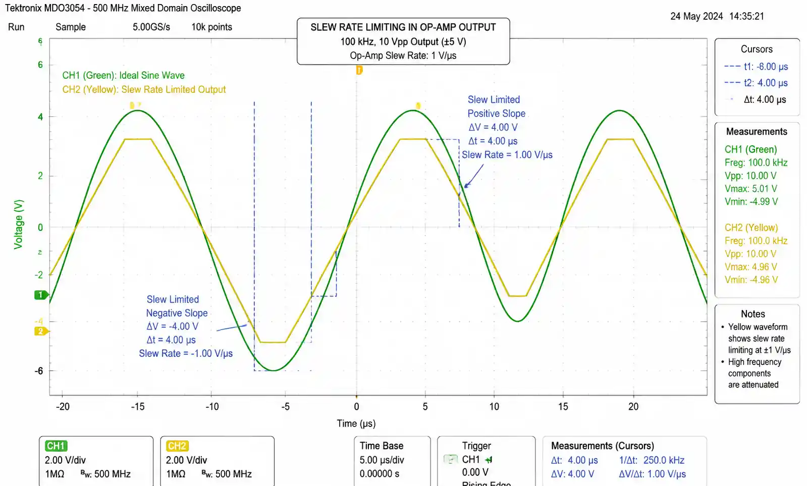
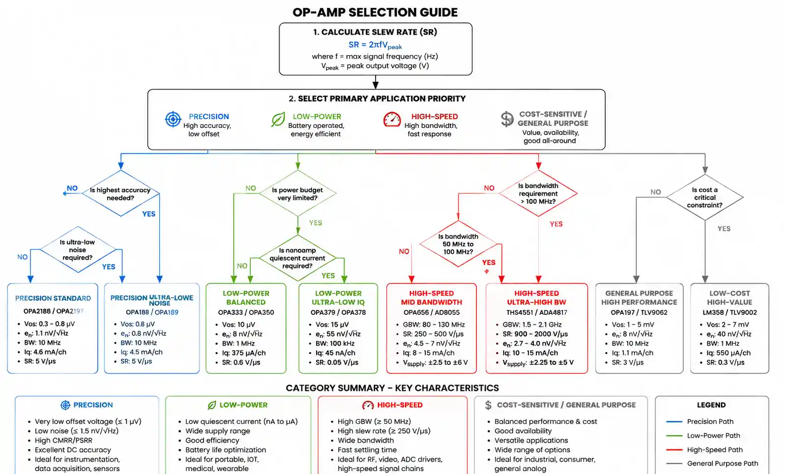
The fundamental relationship between slew rate, frequency, and amplitude is expressed by the equation: SR = 2πfV_peak, where SR is the required slew rate, f is the signal frequency, and V_peak is the peak output voltage. This relationship reveals that slew rate requirements increase linearly with both frequency and amplitude. A 10V peak-to-peak sine wave at 100 kHz requires a minimum slew rate of 3.14 V/µs, while the same amplitude at 1 MHz demands 31.4 V/µs.
Understanding slew rate becomes critical during the design phase because inadequate slew rate cannot be compensated through external circuitry. Unlike bandwidth or gain, which can sometimes be traded off through circuit topology changes, slew rate is fundamentally limited by the op-amp's internal architecture. Selecting an op-amp with insufficient slew rate necessitates complete component replacement, potentially requiring PCB redesign and requalification.
2. Key Technical Parameters Related to Slew Rate
Slew rate interacts closely with several other op-amp specifications, and understanding these relationships enables more informed component selection. Gain-bandwidth product (GBP) and slew rate are often confused, but they represent different limitations. GBP determines small-signal frequency response, while slew rate governs large-signal transient response. An op-amp can have excellent GBP but poor slew rate, or vice versa.
Full-power bandwidth (FPBW) directly relates to slew rate and represents the maximum frequency at which the op-amp can deliver full rated output voltage without slew rate limiting. The relationship is FPBW = SR / (2πV_out), where V_out is the maximum output voltage swing. For example, an op-amp with 10 V/µs slew rate and ±10V output swing has a full-power bandwidth of approximately 159 kHz. Above this frequency, output amplitude must be reduced to avoid distortion.
Settling time represents how quickly the output reaches and stays within a specified error band following a step input. Slew rate dominates the initial large-signal portion of settling time, while small-signal bandwidth and damping characteristics determine final settling. High-speed data acquisition systems require careful analysis of both slew rate for the initial transition and small-signal response for final accuracy.
Supply current and power consumption generally correlate with slew rate capability. Higher slew rate op-amps typically consume more quiescent current because they require higher bias currents in the output stage to charge and discharge internal capacitances quickly. This trade-off becomes particularly important in battery-powered and portable applications where power budget constraints may limit slew rate selection.
The following table summarizes the relationship between slew rate and related specifications:
| Parameter | Relationship to Slew Rate | Design Impact | Typical Trade-off |
|---|---|---|---|
| Gain-Bandwidth Product | Independent; both must meet requirements | Small-signal vs large-signal performance | Higher GBP usually requires more power |
| Full-Power Bandwidth | FPBW = SR / (2πV_out) | Maximum frequency for full output swing | Higher SR extends FPBW proportionally |
| Settling Time | SR determines initial transition speed | Critical for ADC drivers and sample-holds | Faster settling requires higher SR and bandwidth |
| Supply Current | Generally increases with SR | Power consumption and thermal management | High SR typically requires 2-10× more current |
| Output Drive Capability | Higher SR often correlates with higher current | Load driving and capacitive load stability | Strong drivers enable higher SR but consume more power |
Understanding these relationships helps designers avoid the common mistake of selecting an op-amp based solely on one specification while overlooking critical interactions that affect overall circuit performance.
3. How to Calculate Required Slew Rate for Your Application
Accurate slew rate calculation ensures reliable circuit operation with appropriate safety margins. The fundamental equation SR = 2πfV_peak applies to sinusoidal signals, but real-world applications often involve more complex waveforms requiring different analysis approaches.
For sinusoidal signals, calculate the required slew rate by identifying the maximum frequency and output amplitude. If your amplifier must handle a 5V peak signal at 500 kHz, the minimum slew rate is SR = 2π × 500,000 × 5 = 15.7 V/µs. Industry best practice recommends adding a 50-100% safety margin, suggesting a 24-32 V/µs op-amp for this application.
Square wave and pulse applications present different challenges because the theoretical slew rate requirement for perfect square waves is infinite at the transition edges. Practical analysis requires defining acceptable rise time specifications. The relationship between rise time (typically measured from 10% to 90% of final value) and slew rate is approximately SR ≈ 0.8 × V_swing / t_rise. For a 10V swing with 100 ns rise time requirement, the minimum slew rate is approximately 80 V/µs.
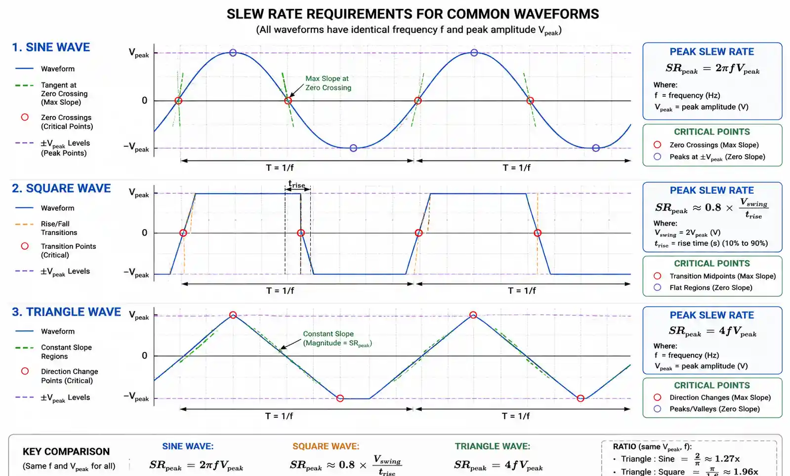
Triangle and sawtooth waveforms have constant slew rate requirements during linear transitions. For a triangle wave, the peak slew rate is SR = 4fV_peak, twice that of an equivalent sine wave. This factor of two arises because triangle waves maintain maximum slope throughout the transition, while sine waves only reach maximum slope at zero crossings.
The following calculation workflow provides a systematic approach to slew rate determination:
Step 1: Identify signal characteristics
- Maximum frequency: f_max
- Peak output voltage: V_peak
- Waveform type: sine, square, triangle, complex
Step 2: Calculate theoretical minimum slew rate
- Sine: SR_min = 2πf_max × V_peak
- Square: SR_min = 0.8 × V_swing / t_rise
- Triangle: SR_min = 4f_max × V_peak
Step 3: Apply safety margin
- Conservative design: SR_required = 2 × SR_min
- Standard design: SR_required = 1.5 × SR_min
- Aggressive design: SR_required = 1.2 × SR_min (only with thorough testing)
Step 4: Verify against application requirements
- Check full-power bandwidth: FPBW = SR / (2πV_out)
- Confirm FPBW exceeds maximum signal frequency
- Verify settling time meets system requirements
Step 5: Consider operating conditions
- Temperature variations affect slew rate (typically ±10-20%)
- Supply voltage variations may reduce available slew rate
- Component aging and production tolerance variations
For composite signals or applications with multiple signal types, calculate the slew rate requirement for each signal component and select the maximum value with appropriate margins.
4. Application-Specific Slew Rate Requirements
Different applications impose varying slew rate demands based on signal characteristics, accuracy requirements, and performance objectives. Understanding these application-specific requirements helps optimize component selection and avoid over-specification or under-specification.
Audio applications typically require moderate slew rates due to the limited bandwidth of human hearing (20 Hz to 20 kHz). A high-quality audio amplifier delivering 20V peak output at 20 kHz requires minimum slew rate of 2.5 V/µs. However, transient intermodulation distortion considerations suggest using op-amps with 5-10 V/µs slew rate for high-fidelity applications. Professional audio equipment often specifies 10-20 V/µs to handle transient peaks cleanly without distortion artifacts.
Data acquisition and ADC driver applications demand careful slew rate analysis because settling time directly affects conversion accuracy. For a 16-bit system, the output must settle to within 0.0015% of the final value before conversion begins. If the ADC samples at 1 MSPS with a 10V input range, the amplifier must transition 10V in less than 1 µs, requiring slew rate exceeding 10 V/µs. Higher resolution systems (18-bit, 20-bit) or faster sampling rates proportionally increase slew rate requirements.
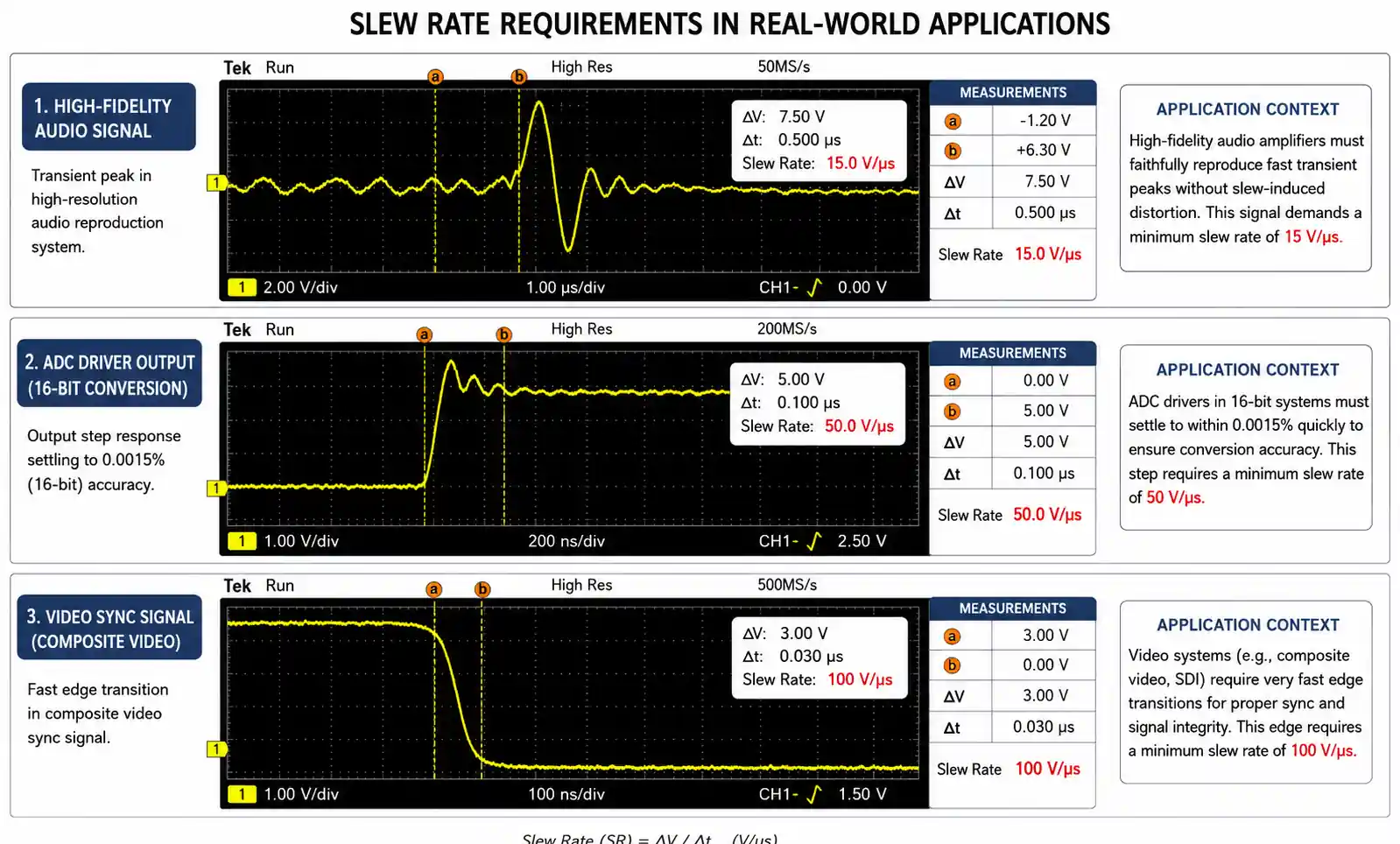
Video and imaging applications involve complex waveforms with fast transitions and varying amplitude. Standard definition video signals require 5-10 V/µs, while high-definition video demands 20-50 V/µs for clean edge reproduction. Medical imaging and industrial inspection systems with high pixel rates may require slew rates exceeding 100 V/µs to maintain image quality during fast sweeps.
Communication systems, particularly RF and IF stages, require very high slew rates when processing modulated carriers. A 10 MHz IF signal with 5V amplitude requires 314 V/µs minimum slew rate. Modern software-defined radio (SDR) applications with wide instantaneous bandwidth often specify op-amps with slew rates exceeding 1000 V/µs to handle wideband signals without distortion.
| Application Category | Typical Frequency Range | Output Amplitude | Recommended Slew Rate | Critical Performance Factor |
|---|---|---|---|---|
| Audio Amplifiers | 20 Hz - 20 kHz | 5V - 20V peak | 5 - 20 V/µs | TIM distortion, transient response |
| Precision Data Acquisition | DC - 100 kHz | 5V - 10V | 10 - 50 V/µs | Settling time, linearity |
| ADC Drivers (12-16 bit) | DC - 10 MHz | 2V - 10V | 20 - 200 V/µs | Settling accuracy, harmonic distortion |
| Video Signal Processing | DC - 10 MHz | 1V - 5V | 20 - 100 V/µs | Rise time, overshoot |
| Photodiode Amplifiers | DC - 1 MHz | 1V - 10V | 5 - 50 V/µs | Transient response, low noise |
| Pulse Amplifiers | 10 kHz - 10 MHz | 5V - 50V | 50 - 500 V/µs | Rise time, edge quality |
| RF/IF Amplifiers | 1 MHz - 100 MHz | 1V - 5V | 100 - 1000+ V/µs | Distortion, dynamic range |
This table provides starting points for component selection, but specific applications may have unique requirements based on system architecture, signal processing algorithms, and performance specifications.
5. Design Considerations and Common Pitfalls
Even with properly calculated slew rate requirements and appropriate component selection, several design factors can compromise performance if not carefully addressed. PCB layout significantly impacts slew rate performance, particularly for high-speed op-amps. Long traces between the op-amp and feedback components introduce parasitic capacitance and inductance that can cause instability, ringing, or oscillation when combined with high slew rate operation.
Capacitive loading represents one of the most common causes of slew rate-related problems. While the op-amp datasheet specifies slew rate under specific load conditions, adding capacitive loads reduces effective slew rate and can cause instability. Many high-speed op-amps become unstable with capacitive loads exceeding 10-50 pF. If driving capacitive loads is unavoidable, inserting a small series resistor (10-50Ω) between the output and load can restore stability, though this introduces additional settling time.
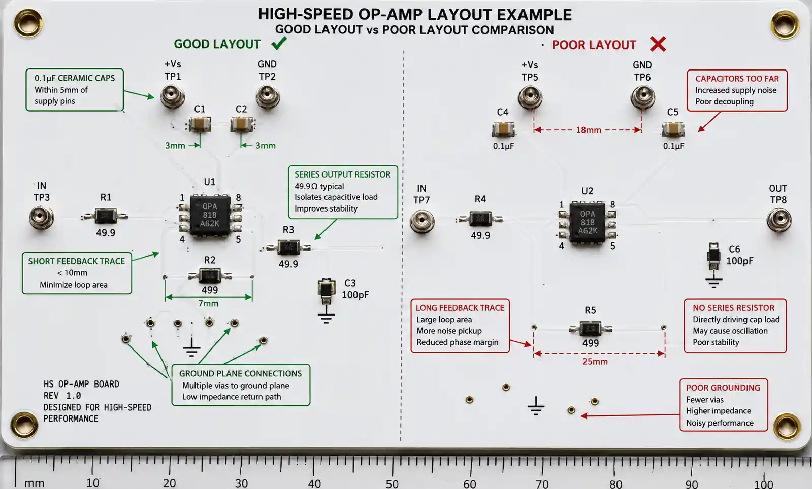
Power supply decoupling critically affects slew rate performance because high slew rates demand rapid current changes from the supply. Inadequate decoupling causes supply voltage variations that reduce available slew rate and introduce distortion. Best practices include placing 0.1 µF ceramic capacitors within 5mm of each supply pin, supplemented by 10 µF tantalum or electrolytic capacitors for lower frequency energy storage. For very high slew rate op-amps (>100 V/µs), consider adding 10 nF or smaller ceramic capacitors in parallel with the 0.1 µF capacitors.
A frequently overlooked pitfall involves operating op-amps near their slew rate limits. Datasheets typically specify slew rate under ideal conditions with specific supply voltages and temperatures. Real-world operation at temperature extremes, reduced supply voltages, or with marginal design margins can reduce effective slew rate by 20-40%. The conservative approach adds 50-100% margin between calculated requirements and specified slew rate capability.
Feedback network design interacts with slew rate performance in non-obvious ways. While feedback resistor values don't directly affect slew rate, parasitic capacitance across the feedback resistor can create high-frequency gain peaking or instability when combined with high slew rate operation. For slew rates above 50 V/µs, keep feedback resistor values below 10 kΩ and minimize parasitic capacitance through careful layout.
The misconception that "more slew rate is always better" leads to over-specification and unnecessary cost or power consumption. Selecting an op-amp with 1000 V/µs slew rate for an audio application provides no performance benefit over a 20 V/µs device but typically consumes 5-10× more power and costs significantly more. Match slew rate selection to actual requirements with appropriate safety margins rather than defaulting to the highest available specification.
Testing and verification of slew rate performance requires appropriate instrumentation and test methodology. Simply measuring rise time on an oscilloscope doesn't fully characterize slew rate performance. Proper testing involves applying large-amplitude signals at frequencies approaching the full-power bandwidth limit while monitoring for distortion, overshoot, and settling behavior. For precision applications, verify settling time to the required accuracy level under worst-case signal conditions.
6. Op-Amp Selection Guide and Performance Comparison
Selecting the optimal op-amp requires balancing slew rate against other specifications including bandwidth, noise, offset voltage, power consumption, and cost. The following comparison organizes common op-amp families by slew rate category to guide initial selection.
| Op-Amp Family | Slew Rate | GBP | Supply Current | Typical Applications | Key Advantages | Considerations |
|---|---|---|---|---|---|---|
| General Purpose (LM358, TL072) | 0.3 - 3 V/µs | 1 - 4 MHz | 0.7 - 2.5 mA | Audio, low-speed sensors, general signal conditioning | Low cost, dual/quad packages, wide availability | Limited high-frequency performance |
| Precision (OP07, OP27) | 0.3 - 2 V/µs | 0.5 - 8 MHz | 2 - 5 mA | Instrumentation, precision measurements, low-offset applications | Ultra-low offset, low drift, excellent DC specs | Lower slew rate trades off for precision |
| High-Speed Audio (NE5532, OPA2134) | 8 - 20 V/µs | 10 - 20 MHz | 4 - 8 mA | Professional audio, high-fidelity amplifiers | Low distortion, good noise performance | Moderate power consumption |
| Fast ADC Drivers (AD8021, OPA695) | 100 - 500 V/µs | 100 - 300 MHz | 5 - 15 mA | ADC drivers, video, high-speed data acquisition | Fast settling, low distortion at high frequency | Requires careful layout, stability considerations |
| Ultra-High-Speed (LMH6702, THS4509) | 1000 - 3000 V/µs | 400 MHz - 2 GHz | 15 - 50 mA | RF/IF, communications, wideband signal processing | Exceptional bandwidth and slew rate | High power consumption, requires RF design expertise |
| Low-Power High-Speed (AD8605, MCP6002) | 1 - 10 V/µs | 2 - 30 MHz | 0.05 - 1 mA | Battery-powered, portable instruments, IoT sensors | Excellent slew rate per milliamp | Lower absolute slew rate vs powered alternatives |
When selecting from multiple candidates that meet slew rate requirements, prioritize based on application-specific critical parameters:
For precision measurement applications: After meeting slew rate requirements, prioritize low offset voltage (< 100 µV), low offset drift (< 1 µV/°C), and low noise. Precision op-amps like the OPA189 or LTC2057 provide excellent DC specifications with moderate slew rates suitable for most measurement applications.
For low-power applications: Focus on slew rate efficiency measured as V/µs per mA of supply current. The AD8605 family delivers 5.5 V/µs from just 100 µA supply current, providing excellent battery life in portable instruments where moderate slew rate suffices.
For high-frequency applications: Consider the relationship between slew rate, bandwidth, and distortion. The AD8021 with 490 V/µs slew rate and 490 MHz bandwidth provides excellent performance for ADC drivers and video applications while maintaining manageable power consumption (6.5 mA typical).
For cost-sensitive applications: When multiple options meet technical requirements, evaluate cost per channel considering single, dual, and quad package options. The TL074 quad op-amp provides four channels with 13 V/µs slew rate at significantly lower system cost than four discrete high-speed op-amps.
Package selection also impacts performance, particularly for high slew rate devices. SOT-23 packages offer small footprint but limited thermal dissipation capability, while SOIC and DIP packages provide better thermal performance. For slew rates exceeding 500 V/µs, consider exposed-pad packages like QFN or MSOP with thermal vias to the ground plane for optimal thermal management.
Supply voltage requirements vary significantly across op-amp families. Ensure the selected device operates efficiently at your available supply voltages. Some high-speed op-amps require ±5V or higher supplies to achieve rated slew rate, while rail-to-rail input/output devices may operate from 2.7V to 5.5V single supply but with reduced slew rate at lower voltages.
7. FAQ
What is the difference between slew rate and bandwidth?
Bandwidth describes small-signal frequency response where the output amplitude is reduced by 3 dB, while slew rate governs large-signal transient response. An op-amp can have wide bandwidth but low slew rate, limiting large-amplitude high-frequency signals. Both specifications must be adequate for your application. For small signals (< 100 mV), bandwidth typically limits performance, while large signals approaching rail-to-rail swing are slew rate limited.
How do I measure actual slew rate in my circuit?
Apply a large-amplitude square wave input (at least 50% of maximum output swing) at a frequency where slew rate limiting occurs. Measure the maximum dV/dt on the rising and falling edges using an oscilloscope with sufficient bandwidth (at least 5× the expected slew rate frequency content). Calculate slew rate from the linear portion of the transition, excluding any initial or final non-linear regions caused by bandwidth limitations.
Can I increase slew rate by changing feedback resistor values?
No, slew rate is fundamentally determined by internal op-amp architecture and cannot be improved through external components. Feedback resistor values affect closed-loop bandwidth and stability but do not change slew rate capability. If measured slew rate is lower than expected, check for inadequate power supply decoupling, excessive capacitive loading, or temperature effects rather than adjusting feedback components.
Why does my op-amp distort at frequencies well below its rated bandwidth?
This typically indicates slew rate limiting rather than bandwidth limitation. Calculate the required slew rate using SR = 2πfV_peak for your actual signal amplitude and frequency. If this exceeds the op-amp's slew rate specification, distortion occurs even though the frequency is within the bandwidth specification. Solution: reduce signal amplitude, decrease frequency, or select an op-amp with higher slew rate.
Do I need the same slew rate for positive and negative transitions?
Most applications require symmetric slew rate, and datasheets typically specify the minimum of positive and negative slew rate. However, some op-amps exhibit asymmetric slew rate where positive and negative transitions differ by 10-30%. For applications sensitive to waveform symmetry (precision pulse generation, data conversion), verify both positive and negative slew rates meet requirements or select devices with guaranteed symmetric performance.
How does temperature affect slew rate?
Slew rate typically decreases with temperature, commonly by 10-20% over the full operating range (-40°C to +125°C). This occurs because internal bias currents decrease with temperature, reducing the current available to charge internal capacitances. For critical applications, verify slew rate specifications at maximum operating temperature or apply additional safety margin (1.5-2×) to account for temperature variations.
What happens if I exceed the slew rate limit?
The output waveform becomes distorted, with fast transitions appearing as linear ramps rather than tracking the input signal. For sine waves, this creates a triangular output during the high slew rate portions. Digital or pulse signals exhibit extended rise and fall times. In precision applications, slew rate limiting causes settling time errors and non-linearity. Prolonged operation at slew rate limits doesn't damage the op-amp but degrades signal quality and system performance.
Can I parallel op-amps to increase slew rate?
No, paralleling op-amps does not increase slew rate. Slew rate is determined by the rate at which the output voltage changes, not the available output current. Paralleling op-amps increases current drive capability and can improve capacitive load driving, but each individual op-amp still has its original slew rate limitation. To achieve higher slew rate, you must select a different op-amp topology with inherently faster internal charging rates.
8. Conclusion and Design Recommendations
Successful op-amp selection based on slew rate requirements combines theoretical calculations with practical design considerations and appropriate safety margins. Begin by accurately calculating the minimum required slew rate using SR = 2πfV_peak for sinusoidal signals or appropriate equations for other waveforms. Apply a safety margin of 1.5-2× to account for temperature variations, component tolerances, and operating margin.
For applications involving multiple signal types or composite waveforms, calculate slew rate requirements for each component and select based on the most demanding case. Verify that the full-power bandwidth (FPBW = SR / 2πV_out) exceeds your maximum signal frequency with appropriate margin. Consider the interaction between slew rate, power consumption, and cost to avoid over-specification that unnecessarily increases system power budget and component cost.
When designing PCBs for high slew rate op-amps, prioritize short feedback paths, adequate power supply decoupling with ceramics within 5mm of supply pins, and controlled impedance for signals with slew rates exceeding 100 V/µs. For precision applications, verify settling time performance through actual testing rather than relying solely on calculations, as parasitic effects and layout considerations significantly impact final performance.
If your design requires slew rates exceeding 50 V/µs, consider consulting application notes from manufacturers like Analog Devices, Texas Instruments, or Linear Technology for layout guidance and stability analysis. For custom or critical applications, request evaluation boards or samples to verify performance in your specific circuit configuration before committing to production. Many distributors offer parametric search tools that allow filtering by slew rate, enabling efficient identification of suitable candidates from their extensive portfolios.