


Pulse Generator Circuit Design and Operation (Engineer-Level Guide)
A pulse generator is a fundamental building block in digital and mixed-signal electronics, used to produce deterministic ON/OFF waveforms for timing, triggering, and validation tasks. This article provides a deeper engineering-level analysis of a pulse generator circuit based on CD4093 (Schmitt NAND) and CD4017 (decade counter). It explains timing theory, signal integrity considerations, pulse-count control logic, and practical implementation techniques. The goal is to help engineers design, tune, and deploy reliable pulse generation systems.
Table of Contents
- 1. What is a Pulse Generator
- 2. System Architecture Overview
- 3. Core Components and Their Roles
- 4. Oscillator Design (Timing Circuit)
- 5. Pulse Gating and Control Logic
- 6. Pulse Counting Using CD4017
- 7. Frequency and Duty Cycle Control
- 8. Finite Pulse Train Generation Mechanism
- 9. Circuit Implementation Guidelines
- 10. Testing and Signal Verification
- 11. Applications
- 12. FAQ
- 13. Conclusion
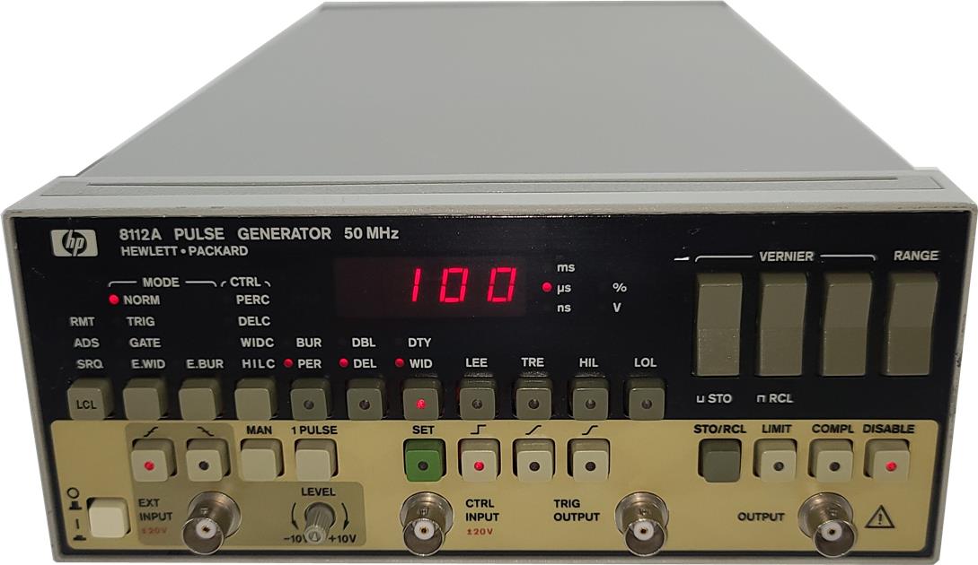
1. What is a Pulse Generator
A pulse generator is an electronic circuit that produces discrete rectangular waveforms characterized by amplitude, frequency, duty cycle, and pulse count. Unlike continuous oscillators, this design supports finite pulse trains, which are critical in sequencing, digital triggering, and state-machine control.
2. System Architecture Overview
The circuit can be decomposed into four functional blocks:
- Oscillator (Clock Source)
- Gate Control Logic (Enable/Disable Pulses)
- Pulse Counter (CD4017)
- Feedback Stop Mechanism
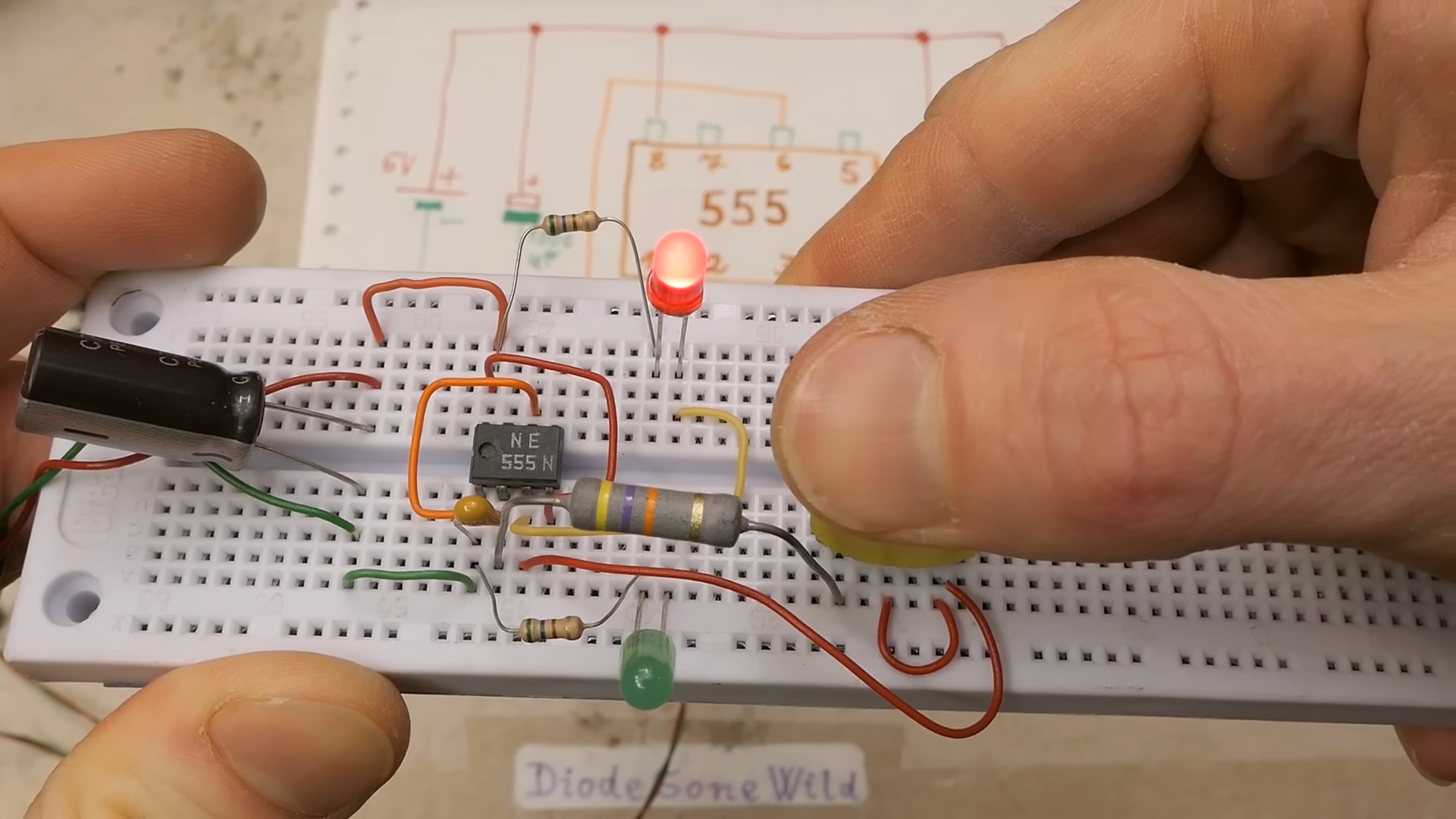
3. Core Components and Their Roles
3.1 CD4093 (Schmitt Trigger NAND)
- Provides hysteresis, improving noise immunity
- Enables stable RC oscillation
- Forms both oscillator and gating logic
3.2 CD4017 Decade Counter
- Johnson counter with 10 decoded outputs
- Advances one output per clock pulse
- Used to count pulses and terminate output
3.3 RC Timing Network
- Determines oscillation frequency
3.4 Switch Matrix (S1–S9)
- Selects desired pulse count
4. Oscillator Design (Timing Circuit)
The oscillator is built using a Schmitt-trigger NAND gate with RC feedback.
Frequency Approximation:
[ f \approx \frac{1}{1.2 \cdot R \cdot C} ]
Engineering Considerations:
- Use low-leakage capacitors
- Avoid high tolerance resistors
- Ensure clean power supply
5. Pulse Gating and Control Logic
The oscillator runs continuously, but output is gated:
- N2 holds output disabled initially
- N3 passes pulses when enabled
This ensures:
- No spurious pulses
- Clean activation
6. Pulse Counting Using CD4017
The CD4017 operates as a sequential state machine:
- Each pulse advances output
- Selected output feeds back to stop pulses
7. Frequency and Duty Cycle Control
- Frequency controlled by RC network
- Duty cycle affected by charge/discharge path
8. Finite Pulse Train Generation Mechanism
Closed-loop operation:
- Generate pulses
- Enable output
- Count pulses
- Stop at target
9. Circuit Implementation Guidelines
- Place RC close to IC
- Add decoupling capacitors
- Avoid long wiring
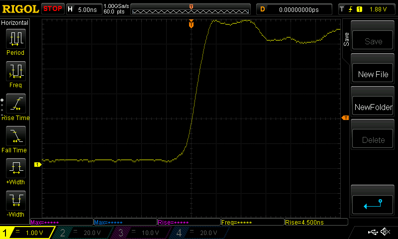
10. Testing and Signal Verification
Verify:
- Frequency
- Pulse width
- Pulse count
Common Faults:
| Issue | Cause |
|---|---|
| No output | Wrong IC orientation |
| Incorrect pulse count | Miswired feedback |
| Unstable signal | Noise / poor grounding |
11. Applications
- Digital system triggering
- Counter testing
- Microcontroller clock injection
- Communication timing validation
- Automated test equipment (ATE)
12. FAQ
Q1: Why use CD4093 instead of a standard NAND gate?
Because it has Schmitt trigger inputs, which provide hysteresis and eliminate oscillation instability caused by noise.
Q2: Can this circuit generate very high frequencies?
No. It is limited by RC time constants and CMOS propagation delay.
Q3: How to increase pulse count beyond 10?
Cascade multiple CD4017 ICs or use binary counters.
Q4: Why is my output jittery?
Likely due to poor power decoupling, long wiring, or noisy environment.
Q5: Can this be replaced by a microcontroller?
Yes, but hardware solutions offer deterministic timing and zero firmware overhead.
13. Conclusion
This pulse generator circuit demonstrates a robust hardware-based method for generating controlled pulse trains using CMOS logic. By combining a Schmitt-trigger oscillator with a decade counter and feedback gating, the design achieves precise control over pulse frequency and count without software dependency. It is a reliable and cost-effective solution for timing-critical and testing applications.