


Core Electronic Modules in Robot Control Systems: Architecture, Interfaces, and Design Trade-offs
Modern robot control systems are built on tightly integrated electronic modules that handle computation, actuation, sensing, communication, isolation, and power delivery. This article provides an engineering-level breakdown of these modules, focusing on system architecture, signal flow, interface design, and real-world component selection. It highlights how microcontrollers, motor drivers, sensors, communication ICs, isolation devices, and power management circuits interact to achieve deterministic, reliable, and efficient robot operation.
Catalog
- 1. System-Level Architecture of Robot Electronics
- 2. Microcontrollers in Robot Control Systems
- 3. Motor Control Electronics and Drive Topologies
- 4. Sensors and Feedback Systems
- 5. Communication Interfaces in Distributed Robotics
- 6. Digital Isolation and Signal Integrity
- 7. Power Management and Energy Control
- 8. Design Integration Considerations
- 9. FAQ
1. System-Level Architecture of Robot Electronics
A robot control system can be understood as a layered architecture:
- Control Layer → Microcontroller (decision-making)
- Drive Layer → Motor drivers and actuators
- Sensing Layer → Motion, position, and environmental sensors
- Communication Layer → Data exchange between distributed nodes
- Power Layer → Energy supply and regulation
- Protection Layer → Isolation and fault protection
Signal flow follows a closed-loop control model:
- Sensors acquire physical data
- MCU processes data and executes control algorithms
- Motor drivers actuate movement
- Feedback returns to the controller
This loop must meet real-time constraints, typically in the range of microseconds to milliseconds.
2. Microcontrollers in Robot Control Systems
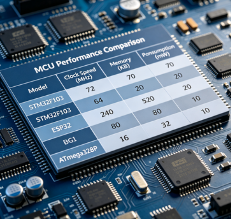
Microcontrollers act as deterministic real-time controllers rather than general-purpose processors. Selection depends on computational complexity, latency requirements, and peripheral integration.
2.1 Entry-Level Control: STM32F103C8T6
- ARM Cortex-M3 core (72 MHz)
- Suitable for basic motion control and simple robots
- Limited DSP capability
Typical use:
- Line-following robots
- Basic motor PWM control
- Low-speed sensor acquisition
2.2 Mid-Range Control: STM32F405RGT6
- Cortex-M4 with FPU (168 MHz)
- Supports DSP operations (PID, filtering)
Key advantages:
- DMA for reduced CPU load
- Multi-interface concurrency
- Real-time multitasking capability
2.3 High-Performance Control: STM32H743VIT6
- Cortex-M7 core (>400 MHz class)
- Advanced cache and pipeline architecture
Engineering significance:
- Enables sensor fusion (IMU + encoder + vision pre-processing)
- Handles high-frequency control loops (>20 kHz)
3. Motor Control Electronics and Drive Topologies
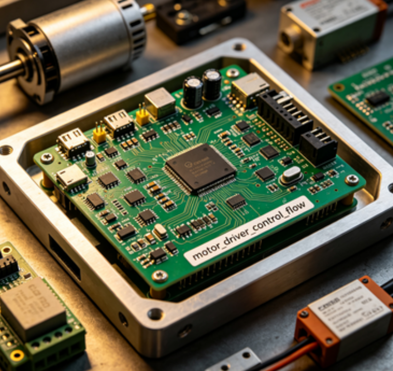
Motor control converts digital control signals into power-stage switching actions.
3.1 PWM Control Expansion: PCA9685PW
- 16-channel PWM generator via I2C
- Offloads timing-critical PWM generation from MCU
Use case:
- Multi-servo robotic arms
3.2 Stepper Motor Control: DRV8825PWPR
- Current-regulated driver with microstepping
- Controls coil energizing sequence precisely
Engineering benefit:
- Reduced vibration
- Improved positional resolution
3.3 Integrated Motor Control: TLE9879GX
- Combines MCU + gate driver + protection
- Reduces PCB complexity and EMI paths
Trade-off:
- Less flexibility vs discrete architecture
4. Sensors and Feedback Systems
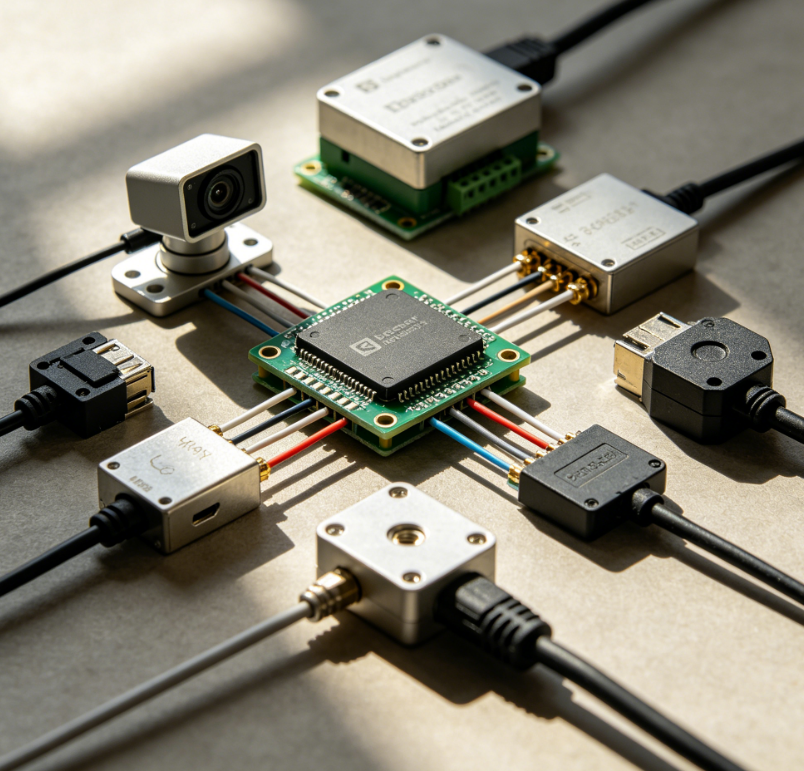
Sensors provide the observability required for closed-loop control.
4.1 Motion Sensing: ADXL345BCCZ
- 3-axis accelerometer
- Measures dynamic and static acceleration
Engineering role:
- Tilt detection
- Vibration monitoring
- Motion tracking
4.2 Position Feedback: AS5600
- Magnetic rotary encoder
- Contactless angle measurement
Advantages:
- No mechanical wear
- High reliability in harsh environments
4.3 Feedback System Design Insight
Combining sensors enables:
- Sensor fusion (e.g., Kalman filtering)
- Higher accuracy than single-sensor systems
5. Communication Interfaces in Distributed Robotics
Distributed robot systems rely on robust communication between nodes.
5.1 CAN Bus Architecture
- Differential signaling for high noise immunity
- Multi-node support with arbitration
5.2 Key CAN Transceivers
| Device | Application | Key Advantage |
|---|---|---|
| SN65HVD230 | General-purpose CAN | Low power consumption |
| MCP2551 | Standard industrial systems | Stable long-distance communication |
| TJA1050 | Harsh industrial environments | High noise immunity |
5.3 Engineering Considerations
- Termination resistance (120Ω typical)
- Bus length vs data rate trade-off
- Fault tolerance and redundancy
6. Digital Isolation and Signal Integrity
Digital isolation prevents ground loops and high-voltage transients from propagating into control circuits.
6.1 Isolation Devices: ADuM1200 / ADuM1201
- Magnetic coupling-based isolation
- No optocoupler aging issues
6.2 Design Benefits
- Improved EMI performance
- Protection against voltage spikes
- Stable communication across domains
6.3 Application Context
- Motor driver isolation
- Industrial robot systems
- Mixed-signal environments
7. Power Management and Energy Control
Power design directly impacts system stability and efficiency.
7.1 DC-DC Conversion
| IC | Type | Function |
|---|---|---|
| LM2596 | Buck Converter | Step-down voltage regulation |
| MP1584 | Buck Converter | High-efficiency voltage conversion |
| XL6009 | Boost Converter | Step-up voltage conversion |
Engineering considerations:
- Switching frequency vs efficiency
- Thermal design
- Output ripple control
7.2 Battery Management Systems (BMS)
- Monitors voltage, current, temperature
- Balances cells in multi-cell batteries
Typical IC:
- BQ24075
7.3 Power Distribution Strategy
- Segregated power domains (logic vs motor)
- Grounding strategy is critical for noise control
8. Design Integration Considerations
8.1 Real-Time Constraints
- Deterministic latency required for control loops
- Interrupt prioritization and scheduling
8.2 Electromagnetic Compatibility (EMC)
- Motor switching introduces noise
- Requires filtering, shielding, and isolation
8.3 Thermal Management
- Power devices generate heat
- Requires PCB thermal design and airflow planning
8.4 Scalability
- Modular design enables distributed robotics
- Standard interfaces (CAN, SPI) improve extensibility
9. FAQ
Q1: Why are microcontrollers preferred over CPUs in robots?
Because MCUs provide deterministic real-time control with low latency and integrated peripherals.
Q2: When should CAN be used instead of UART or SPI?
CAN is preferred in multi-node systems requiring high reliability and noise immunity.
Q3: Is isolation always necessary?
Not always, but it is critical in systems with high power switching or different ground potentials.
Q4: What is the most critical factor in robot power design?
Stable voltage delivery and proper grounding to prevent noise from affecting control logic.