


Sawtooth Wave Generator: Principles, Circuit Design, and Engineering Insights
A sawtooth wave generator is a fundamental signal-generation circuit used in analog systems, waveform synthesis, and timing control. It operates by charging a capacitor linearly and then discharging it rapidly, producing a periodic ramp signal. This article explains the working principle, mathematical model, circuit implementations, and practical design considerations from an engineering perspective.
Table of Contents
- 1. What is a Sawtooth Wave Generator
- 2. Core Operating Principle
- 3. Mathematical Model
- 4. Circuit Implementation Methods
- 5. Practical Circuit Design
- 6. Component Selection
- 7. Sawtooth vs Square Wave
- 8. Optimization Techniques
- 9. Applications
- 10. Conclusion
- FAQ
1. What is a Sawtooth Wave Generator
A sawtooth wave generator produces a periodic waveform with a linear rising slope and a sharp falling edge. This waveform is widely used in systems requiring time-linear behavior.
2. Core Operating Principle
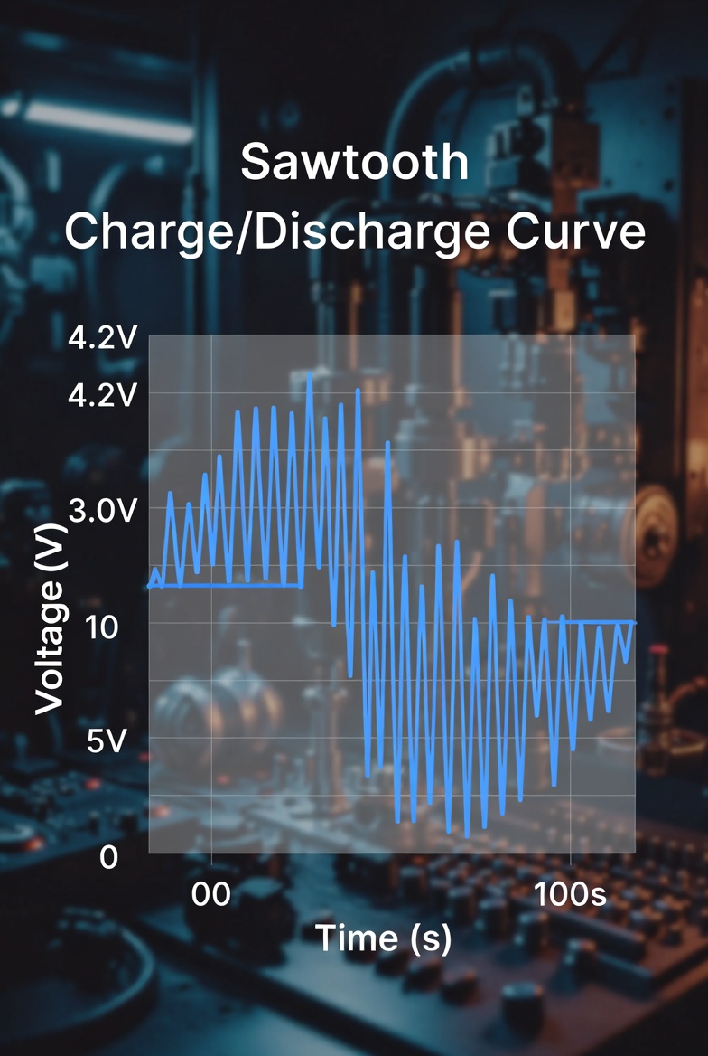
The waveform is generated through a repeating charge–discharge cycle of a capacitor:
- Capacitor charges → voltage rises
- Threshold reached → switching device triggers
- Capacitor discharges rapidly
- Cycle repeats continuously
This behavior forms the characteristic ramp waveform with a fast reset.
3. Mathematical Model
For an ideal sawtooth waveform:
[ V(t)=\frac{V_{max}}{T}t, \quad 0 \leq t < T ]
Where:
- (V_{max}): peak voltage
- (T): period
Engineering Insight
- Constant current → linear waveform
- RC charging → exponential curve (non-ideal)
4. Circuit Implementation Methods
Different implementations trade off complexity vs waveform quality:
RC Relaxation Circuit
- Simplest implementation
- Uses resistor-capacitor charging
- Produces exponential ramp
Constant Current Source
- Provides linear voltage increase
- High accuracy
- Used in precision analog systems
Transistor Switching
- Controls rapid discharge
- Improves waveform sharpness
Op-Amp Integrator
- Generates clean linear ramp
- High stability and precision
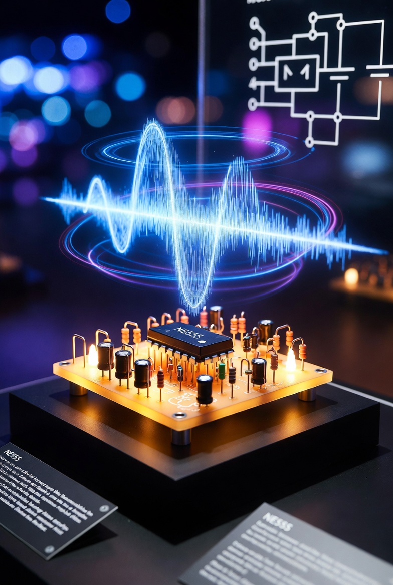
NE555 Timer Method
- Easy to implement
- Low cost
- Moderate accuracy
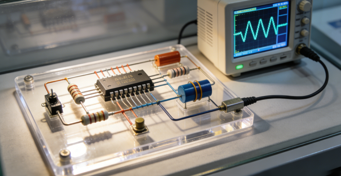
5. Practical Circuit Design
5.1 NE555-Based Sawtooth Generator
The NE555 timer provides a stable timing reference to control charging and discharging cycles of the capacitor.
Engineering Notes
- Easy to build
- Suitable for general-purpose waveform generation
- Limited linearity due to RC charging
5.2 Op-Amp Integrator Sawtooth Generator
An op-amp integrator combined with a comparator produces a highly linear sawtooth waveform.
Engineering Notes
- High precision
- Better linearity
- Suitable for function generators and instrumentation
6. Component Selection
Frequency Control
[ f \approx \frac{1.44}{(R_1 + 2R_2)C} ]
Design Considerations
- Use low-leakage capacitors to maintain waveform accuracy
- Select precision resistors (1% tolerance or better)
- Ensure fast switching devices for sharp discharge
- Choose op-amps with:
- Low input bias current
- High slew rate
- Rail-to-rail capability (if required)
7. Sawtooth vs Square Wave
| Feature | Sawtooth Wave | Square Wave |
|---|---|---|
| Transition | Linear rise + abrupt fall | Instant switching |
| Spectrum | Rich harmonics (all orders) | Odd harmonics only |
| Application | Analog systems | Digital systems |
| Complexity | Moderate | Low |
8. Optimization Techniques
Improve Linearity
- Replace resistor charging with a constant current source
Reduce Noise
- Add decoupling capacitors (e.g., 0.1µF)
- Keep PCB traces short and well-routed
Stabilize Frequency
- Use temperature-stable capacitors (C0G/NP0)
- Use precision resistors
- Maintain stable power supply
Avoid Distortion
- Ensure fast discharge path
- Avoid capacitor leakage and saturation effects
9. Applications
- Signal and function generators
- PWM control systems
- Audio synthesis circuits
- Display scanning systems
- Timing and control circuits
10. Conclusion
A sawtooth wave generator is a key analog circuit that depends heavily on charging linearity and discharge speed. While simple designs such as RC circuits or NE555 timers are sufficient for basic applications, precision systems require constant current sources and op-amp-based integrators. Proper design and component selection significantly improve waveform quality and stability.
FAQ
Q1: Why is my waveform not linear?
Because RC charging produces an exponential curve. Use a constant current source for better linearity.
Q2: How can I sharpen the falling edge?
Reduce discharge resistance or use a faster transistor or switching device.
Q3: Is NE555 suitable for precise waveform generation?
It is suitable for general applications but not ideal for high-precision requirements.
Q4: How can noise be reduced in the circuit?
Use decoupling capacitors, proper grounding, and short PCB traces.
Q5: Why are sawtooth waves widely used?
They provide a time-linear ramp, which is essential for modulation, control, and scanning systems.