


SF6 Circuit Breaker Engineering Principles Working Mechanism and Field Applications in High Voltage Power Systems
SF6 circuit breakers are widely deployed in high-voltage transmission and distribution networks due to their strong arc-quenching capability and high dielectric strength. This article provides a technically focused explanation of SF6 breaker construction, interruption physics, operating mechanisms, design variants, and engineering constraints. The goal is to present a practical engineering understanding rather than a descriptive overview, emphasizing real-world performance considerations, failure modes, and maintenance logic used in power system applications.
Table of Contents
- 1. Engineering Overview of SF6 Circuit Breakers
- 2. SF6 Gas Properties Relevant to Interruption
- 3. Internal Structure and Functional Components
- 4. Arc Interruption Mechanism in SF6 Gas
- 5. Main Design Types of SF6 Circuit Breakers
- 6. Engineering Comparison With Vacuum Circuit Breakers
- 7. Operational Advantages and Technical Limitations
- 8. Application in Power Systems
- 9. Installation and Design Constraints
- 10. Maintenance Strategy and Condition Monitoring
- 11. Failure Modes and Root Causes
- 12. Conclusion
- FAQ
1. Engineering Overview of SF6 Circuit Breakers
An SF6 circuit breaker is a high-voltage switching device designed to interrupt fault currents under extreme electrical stress conditions. Its core function is to extinguish electrical arcs formed during contact separation and restore dielectric strength rapidly enough to prevent restrike.
From an engineering perspective, its performance depends on three coupled systems:
- Gas dynamics under pressure
- Arc plasma behavior during interruption
- Mechanical timing of contact separation
Unlike air or oil-based interrupters, SF6 provides a controlled electro-negative medium that actively absorbs free electrons in the arc zone, accelerating deionization.
2. SF6 Gas Properties Relevant to Interruption
SF6 (sulfur hexafluoride) is not just an insulating medium; it is an active arc-quenching agent.
Key engineering properties:
- High dielectric strength (significantly higher than air)
- Strong electron affinity (forms heavy negative ions)
- High thermal capacity for arc cooling
- Chemical stability under normal operating conditions
- Non-flammable behavior under electrical stress
These characteristics make SF6 suitable for compact high-voltage switchgear designs where insulation distance must be minimized.
3. Internal Structure and Functional Components
Figure 1. Internal structure of an SF6 circuit breaker assembly
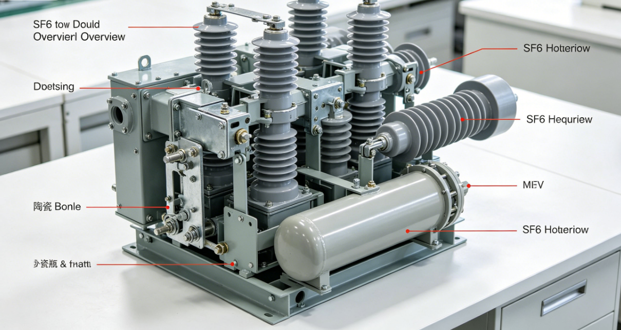
A modern SF6 breaker is composed of tightly integrated mechanical, electrical, and gas systems:
3.1 Current Carrying Path
- Fixed contact
- Moving contact
- Contact fingers designed for low resistance conduction
3.2 Arc Control Region
- Arc chamber (interruption zone)
- Nozzle for gas acceleration
- Arc control geometry optimized for gas flow
3.3 Mechanical Operating System
- Spring or hydraulic drive mechanism
- Linkage system for synchronized contact motion
- Energy storage unit for fast tripping
3.4 Gas Management System
- Pressurized SF6 reservoir
- Sealing system to prevent leakage
- Density monitoring unit for pressure supervision
Engineering reliability is highly dependent on sealing integrity and consistent gas density.
4. Arc Interruption Mechanism in SF6 Gas
Figure 2. Arc extinction process inside SF6 gas environment
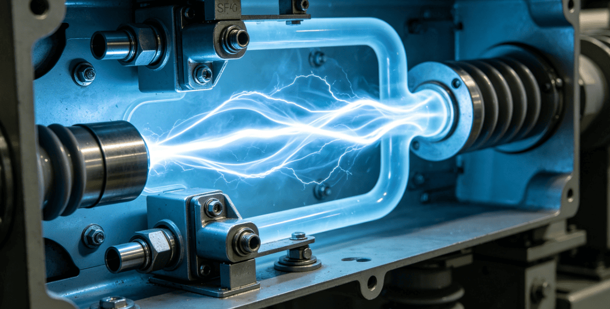
When contacts separate under fault current conditions, an electric arc forms due to ionized plasma. SF6 interruption occurs through a multi-step physical process:
4.1 Arc Formation Phase
Metal vapor and ionized particles form a conductive plasma channel.
4.2 Gas Injection Phase
High-pressure SF6 is forced through a nozzle into the arc region.
4.3 Electron Capture Phase
SF6 molecules attach free electrons, forming heavy negative ions.
4.4 Thermal Collapse Phase
Energy is extracted from the arc column, reducing plasma conductivity.
4.5 Dielectric Recovery Phase
The gap rapidly regains insulation strength, preventing re-ignition.
The key engineering advantage is the combination of thermal quenching and electron attachment in a single medium.
5. Main Design Types of SF6 Circuit Breakers
5.1 Puffer Type
Uses mechanical piston motion to compress SF6 and direct it toward the arc zone. Gas flow is self-generated by contact motion.
5.2 Single Pressure Type
Uses a constant-pressure gas reservoir for both insulation and arc extinction. This design simplifies system architecture and reduces maintenance complexity.
5.3 Double Pressure Type
Separates high-pressure arc extinction gas and low-pressure insulation gas. Although effective, it requires compressors and complex pressure regulation systems.
5.4 Self-Blast Type
Uses arc energy itself to increase local gas pressure, improving interruption efficiency and reducing mechanical energy demand.
6. Engineering Comparison With Vacuum Circuit Breakers
| Technical Parameter | SF6 Circuit Breaker | Vacuum Circuit Breaker |
|---|---|---|
| Interruption Medium | SF6 gas | Vacuum |
| Voltage Range | High and extra-high voltage | Medium voltage |
| Arc Quenching Mechanism | Electron attachment and cooling | Rapid dielectric recovery in vacuum |
| Maintenance Requirement | Gas monitoring required | Low maintenance |
| Environmental Concern | SF6 has high greenhouse potential | Environmentally safer |
| Application Scope | Transmission networks | Distribution systems |
7. Operational Advantages and Technical Limitations
Advantages
- High dielectric strength enables compact design
- Reliable interruption of high fault currents
- Stable switching performance under grid conditions
- Suitable for GIS substations
Limitations
- Environmental impact due to SF6 greenhouse potential
- Requires strict gas sealing integrity
- Higher lifecycle cost compared to vacuum systems
- Needs specialized gas handling procedures
8. Application in Power Systems
SF6 breakers are primarily deployed in:
- High-voltage transmission substations
- Gas-insulated switchgear (GIS) systems
- Power generation plants
- Industrial high-load networks
- Renewable energy grid integration systems
- Urban compact substations
Their main value is space efficiency combined with high interruption reliability.
9. Installation and Design Constraints
Key engineering considerations include:
- Rated voltage coordination with grid level
- Short-circuit breaking capacity
- Ambient temperature and humidity tolerance
- Seismic and mechanical stability requirements
- Gas handling infrastructure availability
- Maintenance accessibility for long-term operation
10. Maintenance Strategy and Condition Monitoring
Figure 3. SF6 breaker monitoring and maintenance system
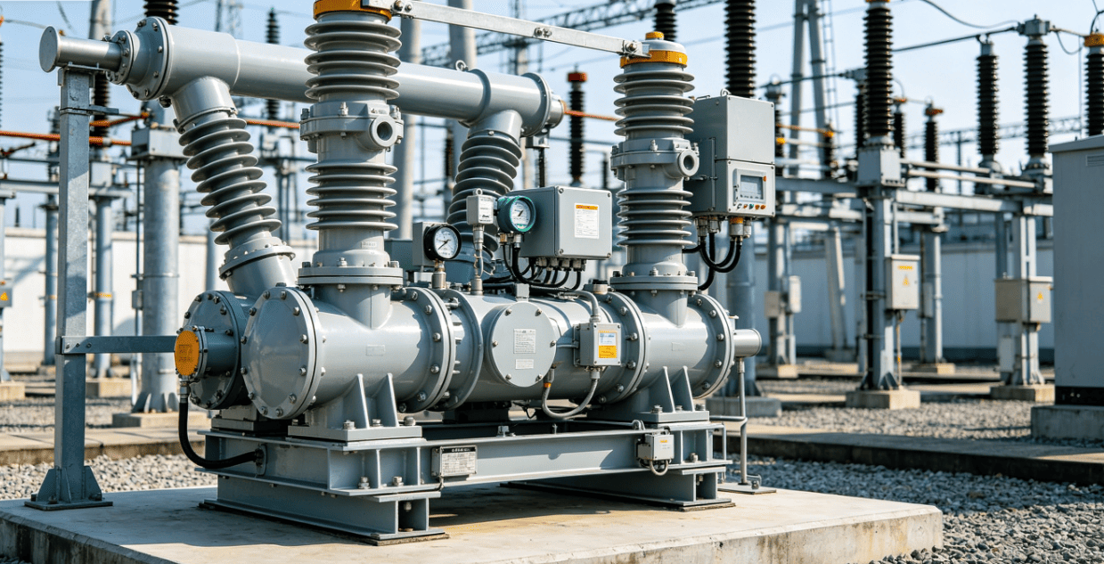
Maintenance is primarily condition-based rather than time-based:
- Continuous SF6 density monitoring
- Leak detection at sealing interfaces
- Contact wear assessment
- Insulation resistance testing
- Mechanical operation timing verification
- Moisture content control in gas system
Modern substations increasingly rely on online monitoring systems to reduce manual inspection frequency.
11. Failure Modes and Root Causes
11.1 Gas Leakage
Most critical failure mode leading to reduced dielectric strength and interruption capability.
11.2 Contact Erosion
Repeated arc exposure causes material degradation and increased resistance.
11.3 Insulation Degradation
Moisture or contamination reduces gas dielectric performance.
11.4 Mechanical Failure
Spring or hydraulic system malfunction prevents proper contact timing.
11.5 Nozzle Blockage
Disrupts gas flow dynamics and weakens arc extinction efficiency.
12. Conclusion
SF6 circuit breakers remain a core technology in high-voltage power systems due to their strong dielectric performance and reliable arc interruption capability. However, their engineering value must now be evaluated alongside environmental constraints and lifecycle cost considerations. In modern grid design, SF6 systems are increasingly combined with digital monitoring and stricter gas management strategies to balance performance with sustainability requirements.
FAQ
1. Why is SF6 used in high-voltage circuit breakers
Because it provides extremely high dielectric strength and efficient arc quenching in compact equipment designs.
2. What is the main technical advantage of SF6 over air
SF6 actively captures free electrons, enabling faster arc extinction than air.
3. Are SF6 circuit breakers still widely used today
Yes, especially in high-voltage transmission and GIS substations, although alternatives are growing.
4. What is the biggest technical concern with SF6 systems
Gas leakage and environmental impact due to high global warming potential.
5. Can SF6 breakers be replaced completely by vacuum breakers
Not in high-voltage transmission systems, as vacuum breakers are mainly suitable for medium voltage levels.