


SF₆ Circuit Breaker: Engineering Principles, Design Trade-offs, and Environmental Constraints
SF₆ circuit breakers are a cornerstone technology in high-voltage (HV) and extra-high-voltage (EHV) power systems due to their superior dielectric strength and arc-quenching capability. This article provides an engineering-level analysis of their operating mechanisms, internal architecture, design variants, and performance trade-offs versus vacuum technology. It also addresses lifecycle considerations, maintenance strategies, and the increasingly critical environmental impact of SF₆ gas, offering practical guidance for specification and deployment in modern grids.
Catalog
- 1. Fundamentals of SF₆ Circuit Breakers
- 2. Arc Physics and Interruption Mechanism
- 3. Internal Structure and Functional Components
- 4. Design Architectures of SF₆ Breakers
- 5. Performance Characteristics and Engineering Advantages
- 6. SF₆ vs Vacuum Circuit Breakers (Technical Comparison)
- 7. Application Scenarios in Modern Power Systems
- 8. Maintenance, Diagnostics, and Reliability Engineering
- 9. Environmental Impact and Regulatory Pressure
- 10. Engineering Selection Guidelines
- 11. FAQ
1. Fundamentals of SF₆ Circuit Breakers
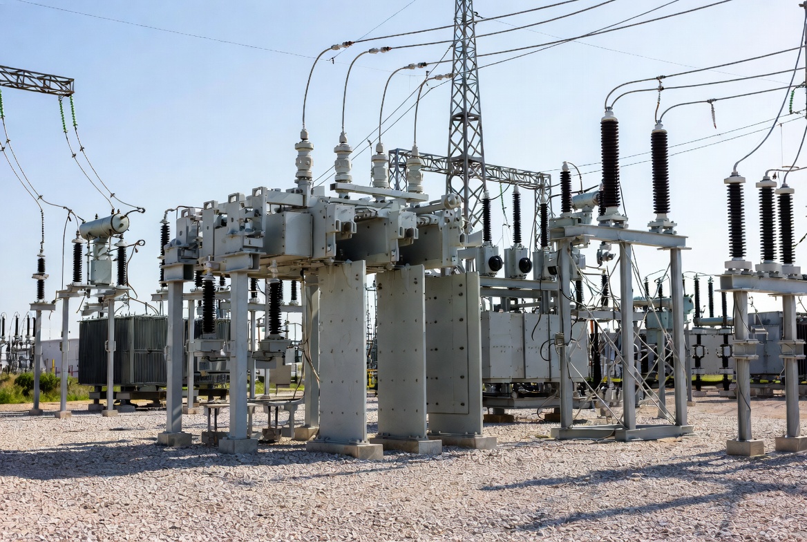
SF₆ circuit breakers utilize sulfur hexafluoride gas as both an insulating medium and an arc-quenching agent. From a dielectric standpoint, SF₆ exhibits approximately 2–3 times the breakdown strength of air under equivalent conditions, enabling compact insulation design.
Key engineering role:
- Interrupt fault currents (up to tens of kA)
- Provide galvanic isolation
- Maintain dielectric integrity post-interruption
Their dominance in HV/EHV systems is primarily due to high interruption reliability under transient recovery voltage (TRV) stress.
2. Arc Physics and Interruption Mechanism
2.1 Arc Formation
When contacts separate under load, a plasma arc forms due to ionized gas and metal vapor. This arc must be extinguished precisely at current zero.
2.2 Role of SF₆ Gas
SF₆ contributes via two dominant mechanisms:
- Electron attachment: SF₆ captures free electrons and reduces plasma conductivity
- Thermal cooling: High thermal conductivity removes arc energy
2.3 Interruption Sequence
- Contact separation initiates arc
- Gas flow (forced or self-generated) cools plasma
- At current zero, dielectric strength recovers
- Successful interruption depends on:
- TRV withstand capability
- Rate of rise of recovery voltage (RRRV)
Failure occurs if dielectric recovery lags TRV.
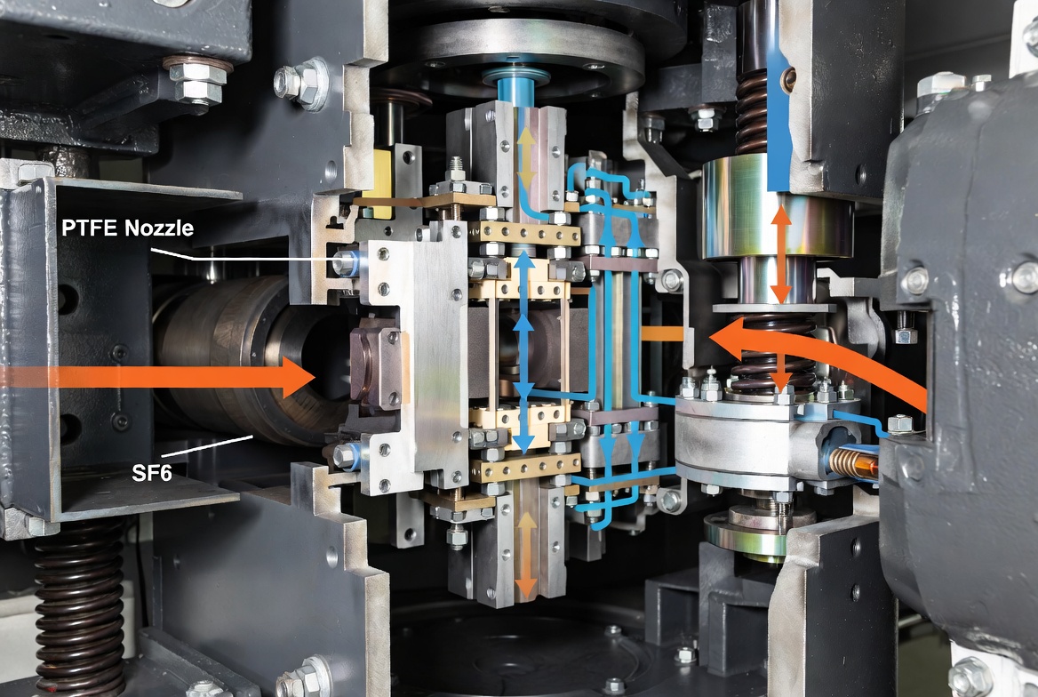
3. Internal Structure and Functional Components
3.1 Interrupter Unit
Core module where arc extinction occurs:
- Optimized nozzle geometry
- Controlled gas dynamics
3.2 Contact System
- Fixed and moving contacts
- Often includes arcing contacts and main contacts separation design
3.3 Gas System
- Pressurized SF₆ chamber (typically 0.3–0.7 MPa)
- Density monitoring is critical for insulation reliability
3.4 Operating Mechanism
- Spring-operated (most common)
- Hydraulic (legacy EHV systems)
- Motor-charged spring systems (modern GIS)
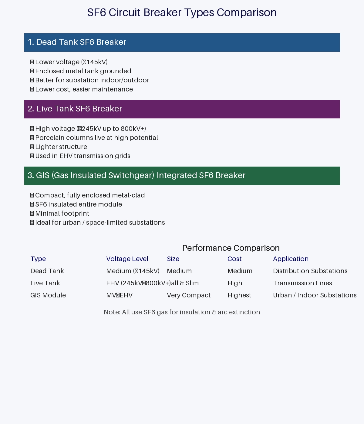
3.5 Enclosure (Live tank / Dead tank)
- Dead tank: grounded enclosure with higher safety
- Live tank: more compact and cost-effective
4. Design Architectures of SF₆ Breakers
4.1 Puffer Type
- Mechanical piston compresses gas
- High reliability but higher operating energy
4.2 Self-Blast Type (Auto-Puffer)
- Uses arc energy to generate gas flow
- Lower drive energy and dominant in modern designs
4.3 Double-Pressure Type
- Separate high and low pressure chambers
- High performance but complex and largely obsolete
4.4 Single-Pressure Type
- Simplified system with controlled gas flow
- Widely used in GIS installations
5. Performance Characteristics and Engineering Advantages
5.1 Electrical Performance
- High breaking capacity (up to 63 kA+)
- Strong TRV performance
- Suitable for long transmission lines and capacitive switching
5.2 Mechanical and Operational
- Long electrical endurance
- Minimal contact erosion
- Fast operation (2–3 cycles interruption)
5.3 System-Level Benefits
- Compact GIS integration
- Reduced footprint in urban substations
- High reliability in harsh environments
6. SF₆ vs Vacuum Circuit Breakers (Technical Comparison)
| Parameter | SF₆ Circuit Breaker | Vacuum Circuit Breaker |
|---|---|---|
| Arc Medium | SF₆ gas | Vacuum |
| Voltage Range | HV / EHV | MV (typically ≤ 36 kV) |
| Arc Extinction | Electron attachment and thermal cooling | Metal vapor condensation |
| TRV Handling | Excellent | Moderate |
| Maintenance | Gas monitoring required | Minimal |
| Environmental Impact | High (greenhouse gas) | Very low |
| Complexity | Higher | Lower |
Engineering insight: Vacuum breakers dominate medium voltage due to simplicity, while SF₆ remains essential for extra-high voltage due to superior insulation and interruption capability under high TRV stress.
7. Application Scenarios in Modern Power Systems
7.1 Transmission Networks
- Backbone grid protection (132 kV – 800 kV)
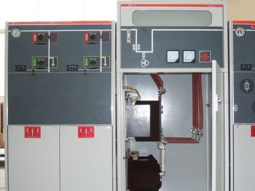
7.2 Gas-Insulated Switchgear (GIS)
- Urban substations
- Offshore platforms
- Underground installations
7.3 Power Generation
- Generator protection
- Transformer switching
7.4 Renewable Integration
- Wind farm collector substations
- Solar HV interconnection
8. Maintenance, Diagnostics, and Reliability Engineering
8.1 Condition Monitoring
- SF₆ density relay (critical protection interlock)
- Moisture content control (ppm level)
- Partial discharge detection
8.2 Failure Modes
- Gas leakage leading to dielectric failure
- Contact wear causing arc instability
- Mechanical fatigue in operating mechanism
8.3 Predictive Maintenance
- Online monitoring integrated with SCADA
- Gas quality analysis including decomposition byproducts
8.4 Safety Engineering
- SF₆ decomposition produces toxic byproducts under arcing
- Proper gas handling procedures and PPE are required
9. Environmental Impact and Regulatory Pressure
9.1 Environmental Characteristics
- Global warming potential approximately 23,500 times CO₂
- Atmospheric lifetime exceeding 3,000 years
9.2 Emission Sources
- Leakage during operation
- Maintenance and gas handling
- End-of-life disposal
9.3 Industry Response
- Development of SF₆-free alternatives such as fluoronitrile mixtures
- Increasing regulatory restrictions globally
10. Engineering Selection Guidelines
10.1 Electrical Parameters
- Rated voltage (kV)
- Short-circuit breaking current (kA)
- TRV requirements
10.2 System Constraints
- GIS or AIS configuration
- Space availability
- Environmental conditions
10.3 Lifecycle Considerations
- Maintenance capability
- Gas handling infrastructure
- Regulatory compliance
10.4 Strategic Recommendation
- Use SF₆ breakers for EHV where technically necessary
- Prefer vacuum or alternative technologies for MV and new installations when feasible
11. FAQ
Q1: Why is SF₆ still used despite environmental concerns?
Because no alternative currently matches its combined dielectric strength and arc-quenching performance in EHV applications.
Q2: What is the most common failure in SF₆ breakers?
Gas leakage leading to reduced dielectric strength and insulation failure.
Q3: Are SF₆-free breakers commercially viable?
Yes, especially in medium voltage and emerging high-voltage ranges, though EHV adoption is still developing.
Q4: How often should SF₆ gas be checked?
Typically continuous monitoring is used, with periodic verification based on maintenance schedules or condition-based strategies.