


Solid State Relay (SSR): The Complete Guide to Modern Electronic Switching
Solid State Relays (SSRs) have revolutionized electronic switching in industrial automation, HVAC systems, and countless other applications. Unlike traditional electromechanical relays with their mechanical contacts and moving parts, SSRs use semiconductor technology to provide faster, quieter, and more reliable switching. This comprehensive guide will help you understand everything about SSRs—from basic operation to advanced applications.
Table of Contents
- What is a Solid State Relay?
- How Do Solid State Relays Work?
- Types of Solid State Relays
- SSR vs Electromechanical Relay: Key Differences
- Advantages of Solid State Relays
- Disadvantages and Limitations
- Common Applications and Uses
- How to Choose the Right SSR
- Installation and Heat Management
- Troubleshooting Common SSR Problems
1. What is a Solid State Relay?
A Solid State Relay (SSR) is an electronic switching device that performs the same function as a traditional electromechanical relay—controlling high-voltage or high-current loads—but without any moving parts. Instead of mechanical contacts, SSRs use semiconductor components such as thyristors, triacs, MOSFETs, or transistors to switch electrical loads ON or OFF.
First invented in 1971 by the Crydom Controls division of International Rectifier, SSRs have become essential components in modern electrical systems. They allow low-power control signals (typically from microcontrollers, PLCs, or logic circuits) to safely switch high-voltage or high-current loads without the mechanical wear and acoustic noise associated with traditional relays.
The key innovation of SSRs is their ability to provide electrical isolation between the control circuit and the load circuit through optical coupling (photocouplers), while switching is performed entirely electronically with no physical movement.
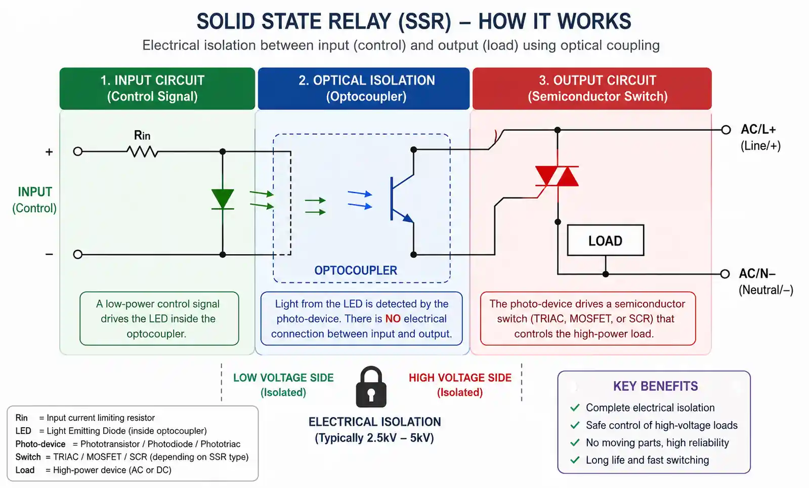
2. How Do Solid State Relays Work?
Understanding how SSRs work requires looking at their three main components:
Input Circuit (Sensor)
The input circuit responds to the control signal, typically a low-voltage DC signal ranging from 3-32VDC. When this control signal is applied, it activates an LED inside the optocoupler, which emits light.
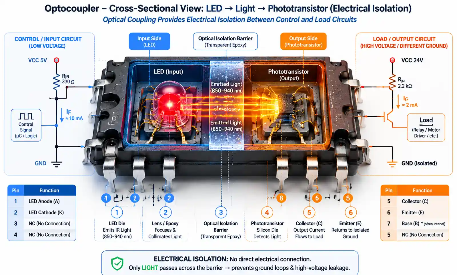
Coupling Mechanism (Optical Isolation)
The optocoupler provides electrical isolation between the input and output circuits. When the LED emits light, it triggers a photosensitive semiconductor (usually a phototransistor or photodiode) on the output side. This optical coupling ensures that the control circuit and load circuit remain electrically isolated, protecting sensitive control electronics from high voltages.
Output Circuit (Electronic Switch)
The output circuit contains semiconductor switching devices that actually control the load. Depending on the type of SSR:
- AC SSRs typically use triacs or back-to-back thyristors (SCRs)
- DC SSRs commonly use MOSFETs or power transistors
When the photosensitive component receives light from the optocoupler, it triggers the output semiconductor device to conduct, completing the circuit and allowing current to flow to the load.
Zero-Crossing vs Random Turn-On
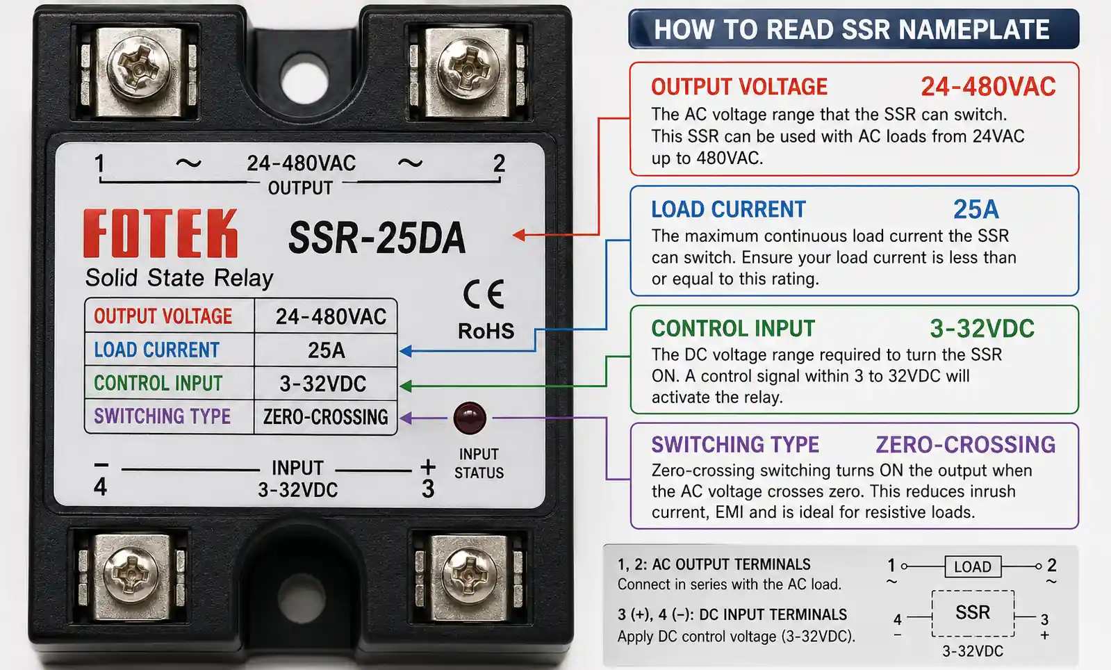
Many AC SSRs feature zero-crossing circuitry, which switches the load only when the AC waveform crosses zero voltage. This minimizes electrical noise and electromagnetic interference (EMI), making zero-crossing SSRs ideal for resistive loads like heaters. Random turn-on SSRs switch immediately when triggered, regardless of the AC waveform phase, making them better for inductive loads like transformers.
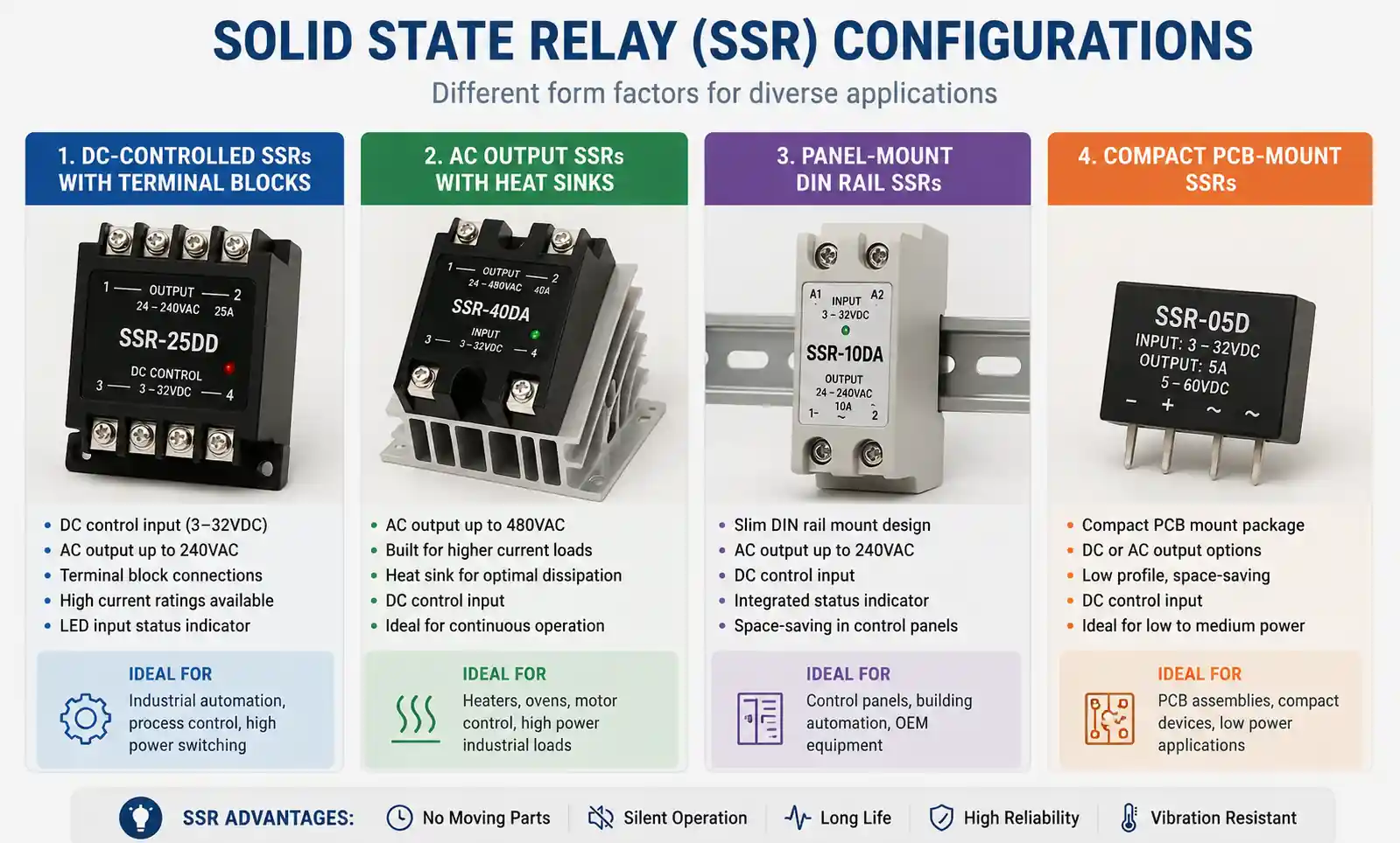
3. Types of Solid State Relays
SSRs come in several configurations based on control signal type, load type, and switching characteristics:
Based on Control Signal
DC-Controlled SSRs: These SSRs accept DC control signals (typically 3-32VDC) and are the most common type. They're ideal for integration with microcontrollers, PLCs, and digital control systems.
AC-Controlled SSRs: Less common, these SSRs accept AC control signals and are used in specific industrial applications.
Based on Load Type
AC Output SSRs: Designed to switch AC loads, these relays use triacs or back-to-back SCRs as switching elements. They're available in both zero-crossing and random turn-on varieties.
DC Output SSRs: Built to switch DC loads, these typically use MOSFETs as the switching element. They offer very low on-state resistance and fast switching speeds.
Based on Configuration
Single-Phase SSRs: Control single-phase AC loads up to 240VAC. Most common in residential and light industrial applications.
Three-Phase SSRs: Designed for three-phase AC loads, containing three separate switching elements synchronized for balanced three-phase control.
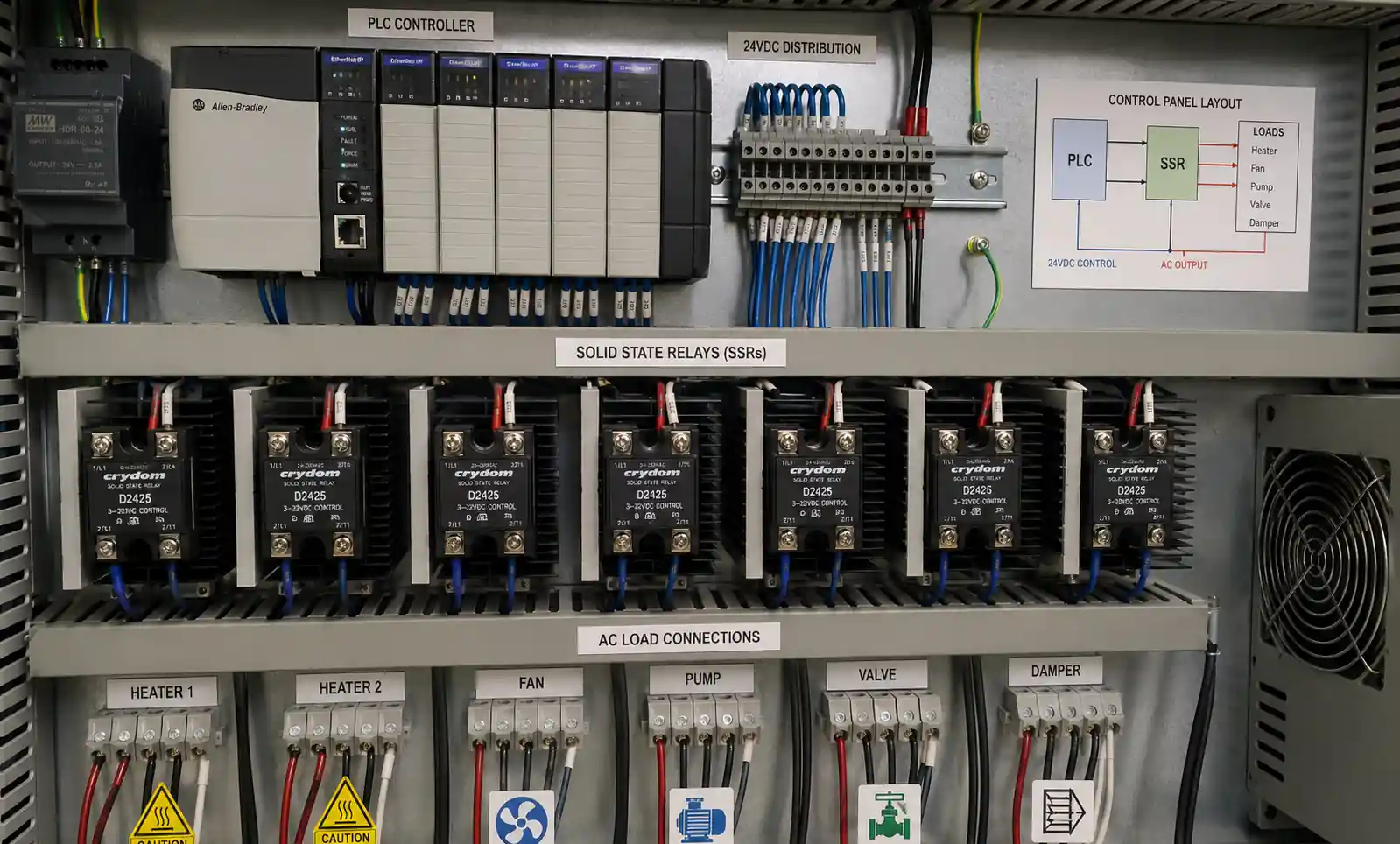
Panel Mount SSRs: Industrial-grade SSRs designed for DIN rail mounting with built-in heat sinks.
PCB Mount SSRs: Compact SSRs designed for direct mounting on printed circuit boards.
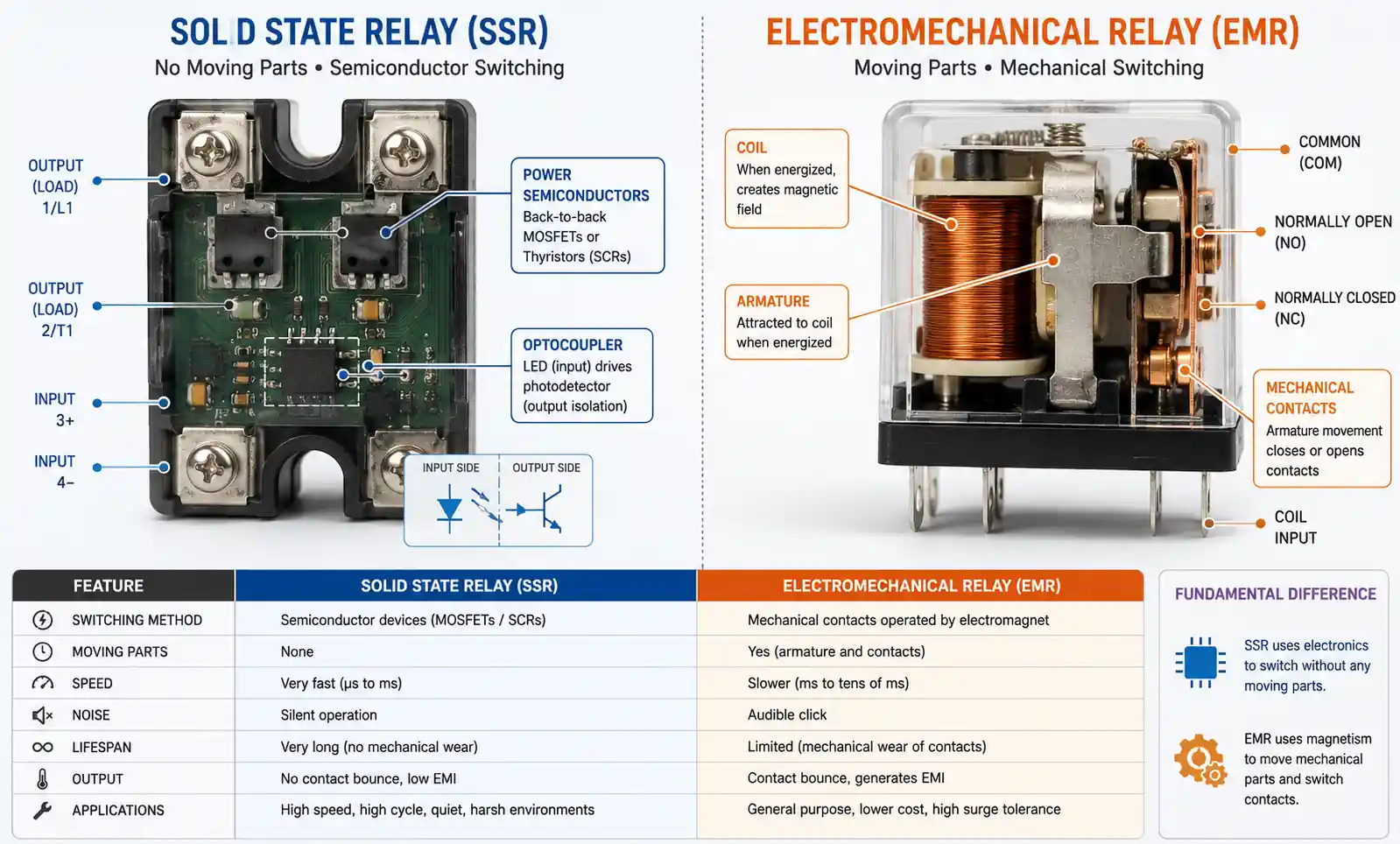
4. SSR vs Electromechanical Relay: Key Differences
Understanding when to use an SSR versus a traditional electromechanical relay (EMR) is crucial for optimal system design.
Solid State Relay Advantages
- No moving parts: Electronic switching eliminates mechanical wear
- Silent operation: No audible clicking or buzzing
- Faster switching: Response times measured in microseconds vs milliseconds
- Longer lifespan: Can exceed 100 million operations vs ~1 million for EMRs
- Lower power consumption: Requires minimal current to trigger (typically 3-25mA)
- Better for high-frequency switching: Can switch thousands of times per second
- No contact bounce: Clean switching without mechanical bounce issues
- EMI/RFI resistant: Especially with zero-crossing types
Electromechanical Relay Advantages
- True isolation when open: Physical air gap provides complete isolation
- Lower on-state resistance: Closed contacts have near-zero resistance
- Better inrush current handling: Can handle higher surge currents
- Lower cost: Generally less expensive, especially at higher current ratings
- More versatile contact configurations: SPDT, DPDT, and other multi-contact arrangements
- No heat sink required: Minimal heat generation in normal operation
Key Technical Differences
| Feature | SSR | Electromechanical Relay |
|---|---|---|
| Switching Speed | Microseconds | Milliseconds |
| Lifespan | 100M+ operations | ~1M operations |
| On-State Resistance | Higher (generates heat) | Near zero |
| Off-State Leakage | Small leakage current | True open circuit |
| Acoustic Noise | Silent | Audible click |
| Shock/Vibration Resistance | Excellent | Moderate |
| Cost (high current) | Higher | Lower |
5. Advantages of Solid State Relays
SSRs offer compelling benefits that make them the preferred choice for many modern applications:
Reliability and Longevity
With no mechanical parts to wear out, SSRs can operate for billions of cycles. This makes them ideal for applications requiring frequent switching, such as temperature controllers, lighting control systems, and motor control applications.
Speed and Precision
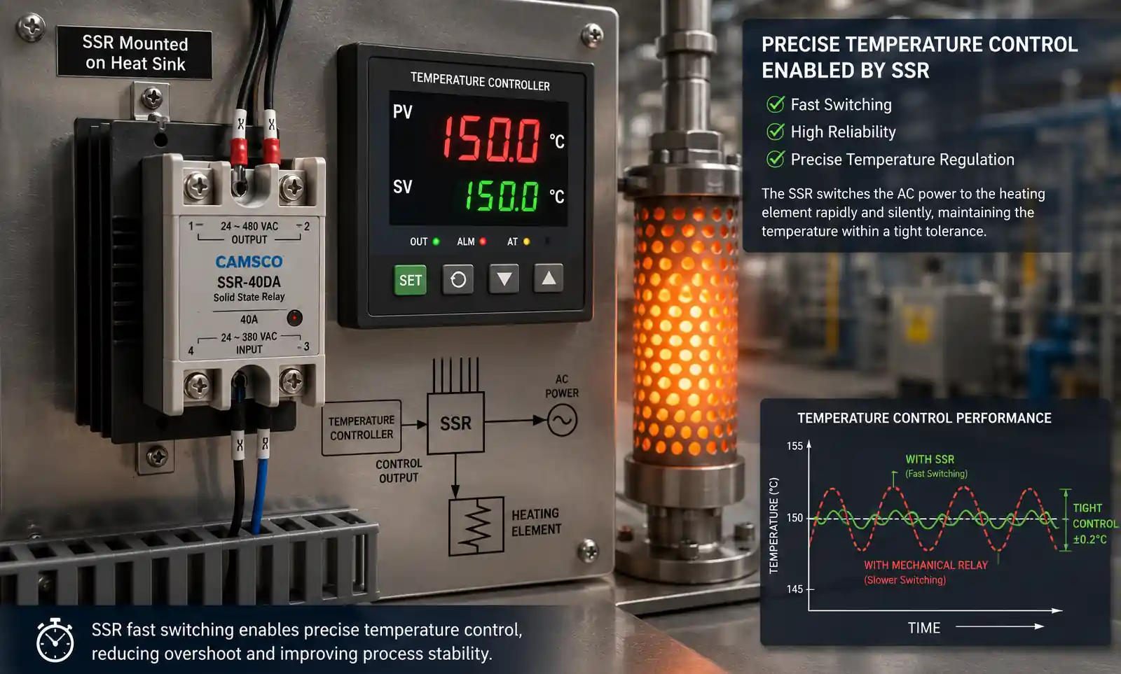
SSRs can switch in microseconds, enabling precise control in high-frequency applications like solar inverters, induction heating, and precision temperature control systems.
Environmental Resistance
SSRs are immune to the effects of shock, vibration, and external magnetic fields that can cause mechanical relays to fail or malfunction. This makes them ideal for mobile equipment, aerospace applications, and high-vibration industrial environments.
Clean Switching
Zero-crossing SSRs produce minimal electromagnetic interference (EMI), making them suitable for sensitive electronic environments. They won't generate voltage spikes that could damage nearby equipment or interfere with communication systems.
Low Maintenance
Once installed with proper thermal management, SSRs require virtually no maintenance. There are no contacts to clean, no mechanical assemblies to lubricate, and no wear-related failures to anticipate.
6. Disadvantages and Limitations
Despite their advantages, SSRs have limitations that must be considered:
Heat Generation
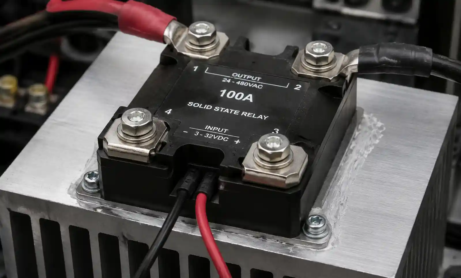
Semiconductors are never completely "on" when conducting. The voltage drop across the switching element creates significant heat that must be dissipated. A typical SSR might have 1-2V drop when conducting 10A, generating 10-20W of heat requiring proper heat sinking.
Higher Initial Cost
SSRs typically cost 2-5 times more than equivalent electromechanical relays, particularly at higher current ratings above 25A.
Off-State Leakage Current
Even when "off," SSRs have a small leakage current (typically 0.5-5mA) flowing through the semiconductor junction. This can be problematic for certain applications requiring absolute zero current when off.
Overcurrent Sensitivity
SSRs can be instantly destroyed by overcurrent conditions. Unlike mechanical relay contacts that might weld together but continue conducting, a failed SSR typically fails shorted or open, requiring replacement.
Voltage Drop
The on-state voltage drop (typically 1-2V) means power is wasted as heat and full source voltage isn't delivered to the load. This is usually not significant but matters in low-voltage DC applications.
Limited Contact Configurations
Most SSRs are normally-open (NO) only. Unlike electromechanical relays that offer SPDT, DPDT, and complex contact arrangements, SSRs typically provide only single-pole normally-open switching.
7. Common Applications and Uses
SSRs excel in numerous industrial, commercial, and consumer applications:
Industrial Automation
SSRs are widely used in factory automation systems, integrated with PLCs, process controllers, and HMIs. They control motors, solenoids, valves, and other actuators with precise timing and high reliability.
HVAC Systems
Commercial and industrial HVAC systems use SSRs for heating control and motor control. Their silent operation, long life, and reliability make them ideal for climate control applications where frequent switching is required.
Temperature Control
Temperature controllers in industrial ovens, plastic injection molding machines, and semiconductor processing equipment use SSRs for precise heating element control. Zero-crossing switching minimizes electrical noise that could interfere with temperature measurement.
Food Service Equipment
Commercial ovens, fryers, and warming equipment use SSRs to control heating elements. Their reliability reduces maintenance costs and downtime in critical food service operations.
Solar Power Systems
SSRs handle rapid switching in solar inverters without generating electromagnetic interference that could affect monitoring equipment. Their ability to switch cleanly at high frequencies makes them essential in modern solar installations.
Lighting Control
Architectural lighting systems, stage lighting, and LED control systems use SSRs for dimming and on/off control. Their silent operation and long life are perfect for these applications.
Medical Equipment
SSRs are used in medical devices where reliability, cleanliness, and EMI control are critical. Their ability to operate in sensitive electronic environments makes them valuable in healthcare applications.
Semiconductor Manufacturing
Clean rooms and semiconductor processing equipment use SSRs because they generate no contact arcing or contamination. Their reliability is essential in high-value manufacturing processes.
8. How to Choose the Right SSR
Selecting the appropriate SSR requires careful consideration of several factors:
Load Characteristics
Identify whether your load is resistive, inductive, or capacitive:
- Resistive loads (heaters, incandescent lamps): Easiest to switch, use zero-crossing SSRs
- Inductive loads (motors, transformers, solenoids): Generate voltage spikes, may require random turn-on SSRs and surge protection
- Capacitive loads (power supplies, filters): High inrush current, require derating
Voltage and Current Ratings
Always select an SSR with ratings exceeding your application requirements:
- Voltage rating: Choose an SSR rated at least 1.5-2× your maximum supply voltage
- Current rating: Derate by 50-80% for safety and longevity. If your load draws 10A, use a 15-20A SSR
Control Signal Compatibility
Ensure the SSR's input voltage range matches your control system. Common input ranges include:
- 3-32VDC (most common, compatible with most logic systems)
- 4-32VDC
- 10-30VDC
- 90-280VAC (for AC control signals)
Switching Type
Choose between:
- Zero-crossing: For resistive loads requiring clean switching with minimal EMI
- Random turn-on: For inductive loads or phase control applications
Thermal Considerations
Calculate expected heat dissipation and select appropriate heat sinking. The power dissipated equals the SSR's voltage drop multiplied by load current (P = V × I). A typical SSR with 1.5V drop at 10A dissipates 15W requiring adequate heat sinking.
Form Factor
Consider your mounting requirements:
- Panel mount: For DIN rail or chassis mounting with integrated heat sink
- PCB mount: For circuit board integration
- Hockey puck: For high-current industrial applications
Additional Features
Consider optional features:
- Built-in fusing: Protects against overcurrent
- LED indicators: Shows switching status
- Integrated heat sink: Simplifies installation
- Reverse input protection: Prevents damage from incorrect wiring
9. Installation and Heat Management
Proper installation is critical for SSR reliability and longevity.
Heat Sink Selection
Heat dissipation is the most critical factor in SSR installation. Follow these guidelines:
Calculate Power Dissipation: Power (W) = Voltage Drop × Load Current
For example: 1.5V drop at 15A = 22.5W heat generation
Select Appropriate Heat Sink:
- Consult manufacturer's thermal resistance curves
- Ensure heat sink can maintain junction temperature below maximum rating (typically 125°C)
- Allow adequate airflow around heat sink
- Consider forced air cooling for high-power applications
Proper Mounting:
- Apply thermal compound between SSR and heat sink
- Ensure flat, clean mating surfaces
- Use proper mounting torque (typically 6-10 in-lbs)
- Mount heat sink with fins oriented vertically for best convection
Surge Protection
Protect SSRs from voltage spikes and transients:
- Install MOV (Metal Oxide Varistor) or TVS (Transient Voltage Suppressor) across the load
- Use RC snubbers for inductive loads
- Consider input protection for electrically noisy environments
Wiring Best Practices
- Use wire gauge appropriate for load current
- Keep input wiring separate from output wiring to prevent interference
- Use shielded cable in electrically noisy environments
- Ensure proper grounding
- Observe polarity on DC SSRs
Environmental Considerations
- Operating temperature range: Typically -30°C to +80°C
- Keep away from moisture unless using sealed/conformal coated units
- Protect from dust and contaminants
- Allow adequate ventilation
10. Troubleshooting Common SSR Problems
Understanding common failure modes helps diagnose and prevent SSR problems:
Overheating
Symptoms: SSR fails prematurely, load doesn't turn on consistently, or plastic housing shows signs of heat damage.
Causes:
- Inadequate heat sinking
- Operating current exceeds rating
- Poor thermal interface (no thermal compound)
- Blocked airflow
Solutions:
- Install larger heat sink
- Add forced air cooling
- Derate load current
- Apply thermal compound
- Verify heat sink mounting torque
Load Won't Turn Off
Symptoms: Load remains energized when control signal is removed.
Causes:
- SSR failed shorted (most common failure mode)
- Excessive voltage spike damaged output device
- Overcurrent event destroyed semiconductor
Solutions:
- Replace SSR
- Install surge protection (MOV or snubber)
- Verify load current doesn't exceed rating
- Check for inductive load voltage spikes
Load Won't Turn On
Symptoms: No output when control signal applied.
Causes:
- No control signal reaching SSR input
- Control voltage below SSR pickup threshold
- SSR failed open
- Incorrect wiring polarity (DC SSRs)
Solutions:
- Verify control signal with multimeter
- Check wiring connections
- Verify control voltage meets SSR specifications
- Check output across SSR with load disconnected
- Replace SSR if failed
Erratic Switching
Symptoms: Load turns on/off unpredictably, doesn't respond consistently to control signals.
Causes:
- Control signal voltage near SSR threshold
- Electrical noise on control lines
- Overheating causing temperature-dependent behavior
- Poor connections
Solutions:
- Ensure control voltage well above SSR pickup voltage
- Use shielded cable for control signals
- Add filtering capacitor to control input
- Improve heat sinking
- Check all connections
Premature Failure
Symptoms: SSR fails after short operational period.
Causes:
- Insufficient current rating (undersized)
- Inadequate heat dissipation
- Voltage spikes from inductive loads
- Exceeding voltage rating
Solutions:
- Derate SSR to 50-80% of rated current
- Improve thermal management
- Install surge protection
- Use SSR with higher voltage rating
- Add RC snubber for inductive loads
Conclusion
Solid State Relays represent a significant advancement in electronic switching technology, offering superior reliability, speed, and longevity compared to traditional electromechanical relays. While they have limitations—particularly regarding heat generation and initial cost—their advantages make them the preferred choice for modern automation, HVAC, temperature control, and countless other applications.
Success with SSRs requires proper selection based on load characteristics, adequate thermal management, and appropriate surge protection. By understanding the fundamentals covered in this guide and following best practices for installation and operation, you can leverage SSRs to create reliable, efficient, and long-lasting electrical control systems.
Whether you're designing industrial automation systems, upgrading HVAC equipment, or developing consumer electronics, SSRs offer a proven, reliable solution for electronic switching in demanding applications.