


Split Phase Induction Motor: Engineering-Level Analysis, Design, and Practical Considerations
A split phase induction motor is a single-phase asynchronous machine that achieves self-starting capability by creating an artificial phase displacement between two stator windings. While structurally simple, its electromagnetic behavior, thermal constraints, and torque characteristics impose clear engineering trade-offs. This article provides a deeper technical perspective on its construction, operating principles, torque production, performance limits, and real-world design considerations.
Table of Contents
- 1. Definition and Operating Concept
- 2. Electromagnetic Structure and Design
- 3. Working Principle and Phase Splitting Mechanism
- 4. Torque Production and Speed Characteristics
- 5. Thermal Behavior and Efficiency
- 6. Design Trade-offs and Engineering Constraints
- 7. Applications and Selection Criteria
- 8. Comparison with Other Single-Phase Motors
- 9. Maintenance and Failure Analysis
- 10. FAQ
1. Definition and Operating Concept
A split phase induction motor is a single-phase induction motor that uses two stator windings with dissimilar impedance characteristics to create a phase displacement between currents. This phase shift generates a weak rotating magnetic field sufficient to produce starting torque.
Unlike three-phase machines, which inherently produce a rotating field, single-phase motors require auxiliary means to break the pulsating field symmetry.
2. Electromagnetic Structure and Design
2.1 Stator Configuration
-
Main winding (run winding)
- High inductive reactance (Xₗ dominant)
- Designed for continuous duty
-
Auxiliary winding (start winding)
- High resistance-to-reactance ratio (R/X high)
- Optimized for phase shift, not efficiency
-
Spatial displacement: 90 electrical degrees
2.2 Rotor Design
- Squirrel cage rotor
- Aluminum or copper bars shorted by end rings
- No external electrical connection
- Robust and low maintenance
.png)
3. Working Principle and Phase Splitting Mechanism
When connected to a single-phase AC supply:
-
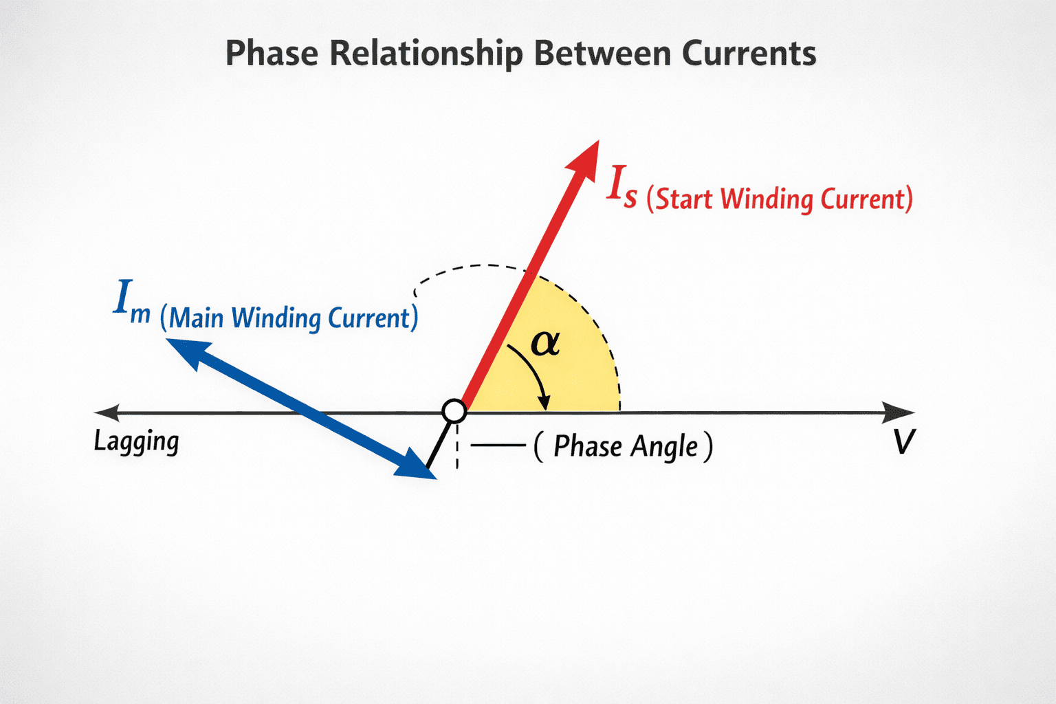
Main winding current: [ I_m \approx \frac{V}{Z_m}, \quad \text{lagging due to inductance} ]
-
Start winding current: [ I_s \approx \frac{V}{Z_s}, \quad \text{closer to in-phase due to higher resistance} ]
This creates a phase angle ( \alpha ) (typically 25°–40°).
Starting Torque Expression
[ T_{start} \propto I_s \cdot I_m \cdot \sin(\alpha) ]
This is significantly lower than capacitor-start motors because the phase angle is limited.
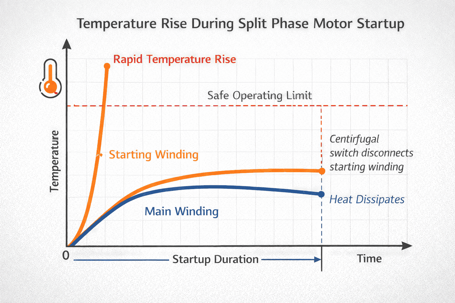
Once the rotor reaches ~75% synchronous speed:
- A centrifugal switch disconnects the start winding
- The motor continues as a single-phase induction motor
4. Torque Production and Speed Characteristics
4.1 Key Performance Metrics
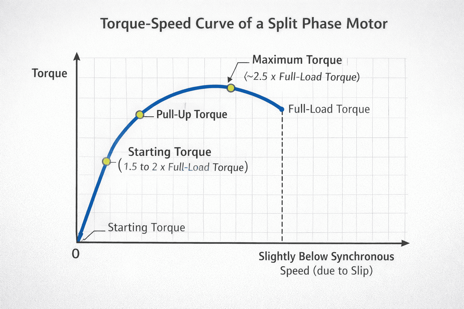
- Starting torque: 1.5–2.0 × rated torque
- Breakdown torque: ~2.5 × rated torque
- Starting current: 6–8 × rated current
- Slip at full load: 3–5%
4.2 Torque-Speed Behavior
- Moderate starting torque
- Smooth acceleration after startup
- Limited capability for high-inertia loads
5. Thermal Behavior and Efficiency
5.1 Thermal Constraints
- Start winding is not rated for continuous operation
- High I²R losses due to:
- Elevated resistance
- High inrush current
5.2 Failure Risks
- Prolonged startup → insulation degradation
- Frequent cycling → thermal fatigue
5.3 Cooling Considerations
- Ventilated frame design
- Shaft-mounted cooling fan
- Thermal overload protection (bimetal or electronic)
6. Design Trade-offs and Engineering Constraints
| Parameter | Design Impact |
|---|---|
| Start winding resistance | Improves phase shift but increases copper loss |
| Phase angle (α) | Directly determines starting torque capability |
| Switch cut-out speed | Affects protection timing and efficiency |
| Conductor size | Thermal performance vs material cost trade-off |
Key Insight
Maximizing starting torque without a capacitor is fundamentally limited by achievable phase displacement using resistance alone.
7. Applications and Selection Criteria
Suitable Loads
- Low starting torque requirement
- Stable speed demand
- Infrequent start-stop cycles
Typical Applications
- Fans and blowers
- Washing machines
- Small machine tools
- Centrifugal pumps
Selection Guidelines
Use split phase motors when:
- Cost sensitivity is critical
- Load inertia is low
- Simplicity and reliability are priorities
8. Comparison with Other Single-Phase Motors
| Motor Type | Starting Torque | Efficiency | Complexity |
|---|---|---|---|
| Split Phase Motor | Medium | Moderate | Low |
| Capacitor Start Motor | High | Higher | Medium |
| Permanent Split Capacitor (PSC) | Low | High | Medium |
| Shaded Pole Motor | Very Low | Low | Very Low |
Engineering Perspective
Split phase motors provide a balance between cost and performance but are outperformed by capacitor-based designs in high-torque scenarios.
9. Maintenance and Failure Analysis
9.1 Common Failure Modes
-
Centrifugal switch failure
- Causes continuous energization of start winding
-
Winding insulation breakdown
- Due to thermal stress accumulation
-
Bearing wear
- Leads to vibration and mechanical losses
9.2 Diagnostic Indicators
- Humming without rotation → start winding issue
- Excess current draw → overload or rotor fault
- Overheating → ventilation or duty cycle problem
9.3 Preventive Measures
- Limit frequent starts
- Ensure proper airflow
- Use overload protection devices
- Schedule periodic inspections
10. FAQ
Q1: Why is the starting torque limited in split phase motors?
Because the phase shift is achieved using resistance rather than a capacitor, the phase angle remains relatively small, limiting torque generation.
Q2: What happens if the centrifugal switch fails?
The start winding stays energized, leading to rapid overheating and potential insulation failure.
Q3: Can this motor drive heavy loads?
No. It is not suitable for high-inertia or heavy starting loads. Capacitor-start motors are preferred in such cases.
Q4: Why is starting current so high?
At startup, there is no back EMF, and both windings draw high current simultaneously, resulting in significant inrush current.
Q5: How can motor lifespan be improved?
Reduce frequent starts, maintain cooling conditions, and ensure proper electrical protection.
Conclusion
The split phase induction motor remains a practical solution for low-cost, light-duty applications. However, its inherent limitations in starting torque and thermal performance require careful engineering consideration. Proper application matching, thermal management, and protection strategies are essential to ensure reliable and efficient operation over its service life.