


A Complete Guide to Temperature Switch: Wiring, Installation, and Protection Circuits
Temperature switches play a critical role in protecting equipment from thermal damage across automotive, industrial, and HVAC applications. This guide provides engineers and procurement managers with practical insights into temperature switch selection, wiring configurations, installation best practices, and protection circuit design. Whether you're designing an engine cooling system or specifying thermal protection for industrial machinery, understanding these fundamentals will help you avoid common pitfalls and ensure reliable operation.
Table of Contents
- What is a Temperature Switch and How Does It Work
- Key Technical Parameters Explained
- Temperature Switch Types and Selection Criteria
- Wiring Configurations and Circuit Design
- Installation Best Practices and Common Mistakes
- Protection Circuit Design Considerations
- Frequently Asked Questions
- Conclusion and Next Steps
1. What is a Temperature Switch and How Does It Work
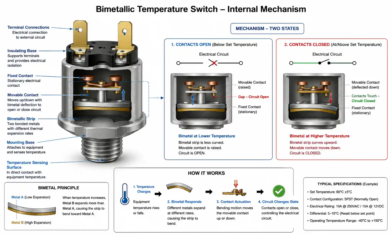
A temperature switch is an electromechanical or solid-state device that automatically opens or closes electrical contacts when a monitored temperature reaches a predetermined setpoint. Unlike temperature sensors that provide continuous analog or digital readings, temperature switches deliver discrete on/off control signals, making them ideal for protection circuits, alarm systems, and simple control loops.
The operating principle varies by technology. Bimetallic switches use two bonded metals with different thermal expansion coefficients. When temperature rises, differential expansion causes the bimetallic strip to bend, mechanically actuating electrical contacts. Gas-filled or capillary switches rely on thermal expansion of sealed gas or liquid to move a diaphragm or bellows, which triggers contact closure. Solid-state temperature switches use semiconductor sensors and comparator circuits to provide logic-level outputs without mechanical contacts.
Temperature switches are specified by setpoint temperature, contact configuration (normally open or normally closed), switching capacity, reset type (automatic or manual), and response time. In automotive cooling systems, a temperature switch mounted in the coolant passage activates the radiator fan when coolant temperature exceeds the setpoint, typically 92-95°C. In industrial applications, temperature switches provide overheat protection for motors, pumps, bearings, and hydraulic systems.
The key advantage over continuous monitoring is simplicity. A temperature switch requires no ADC, microcontroller, or complex software—just power, load, and setpoint configuration. This makes it cost-effective for applications where discrete thermal protection is sufficient.
2. Key Technical Parameters Explained
Understanding datasheet parameters is essential for proper temperature switch selection. The following specifications directly impact design reliability and should be verified against your application requirements.
Setpoint Temperature: The temperature at which the switch changes state. Specified as a nominal value with tolerance, typically ±2°C to ±5°C for bimetallic types, ±1°C or better for solid-state types. In precision applications, verify actual setpoint calibration rather than relying solely on nominal ratings.
Differential (Deadband): The temperature difference between switch-on and switch-off points. A switch with 90°C setpoint and 5°C differential will close contacts at 90°C and reopen at 85°C during cooling. Larger deadband prevents rapid cycling but reduces control precision. Industrial motor protection typically uses 10-15°C deadband to avoid nuisance trips during normal load variations.
Contact Rating: Maximum current and voltage the switch contacts can reliably handle. Specified separately for resistive, inductive, and lamp loads. Inductive loads (motors, solenoids, relays) have much lower ratings due to high inrush current and contact arcing. Always derate by 50% for inductive loads or use contact protection networks.
Response Time: Time required for the switch to actuate after temperature crosses setpoint. Bimetallic switches typically respond in 5-30 seconds depending on mass and contact force. Capillary types respond faster (1-5 seconds) due to lower thermal mass. Response time affects protection effectiveness—faster response prevents temperature overshoot but increases susceptibility to transient thermal events.
Electrical Life: Number of switching cycles the contacts can withstand at rated load. Mechanical life (no load) is typically 10-100× higher than electrical life. Switching 10A resistive loads may provide 100,000 cycles, while 5A inductive loads might reduce life to 10,000 cycles. For long-life applications, consider solid-state switches with no wear mechanism.
Temperature Rating: Ambient and storage temperature limits. The switch body must survive higher temperatures than the setpoint—a 120°C setpoint switch should have 150°C+ body rating for automotive underhood use.
| Parameter | Bimetallic | Capillary | Solid-State |
|---|---|---|---|
| Setpoint Accuracy | ±3 to ±5°C | ±2 to ±3°C | ±1°C |
| Differential | 5-15°C | 3-8°C | 0.5-3°C (adjustable) |
| Response Time | 10-30 sec | 1-5 sec | <1 sec |
| Contact Rating | 10-16A @ 250VAC | 5-10A @ 250VAC | Logic level (requires relay) |
| Electrical Life | 10K-100K cycles | 50K-200K cycles | Unlimited (no contacts) |
| Cost | Low | Medium | Medium-High |
This table shows typical performance trade-offs. Bimetallic switches dominate cost-sensitive applications with moderate precision requirements. Capillary switches suit applications needing remote sensing or faster response. Solid-state types excel in high-cycle or precision control applications where an external relay handles load switching.
When selecting between types, prioritize the parameters most critical to your application. A motor protection circuit requires high contact rating and reliability over precision. A battery thermal management system needs fast response and tight differential. Always verify actual datasheet specifications against this guidance—individual products vary significantly.
3. Temperature Switch Types and Selection Criteria
Choosing the right temperature switch type depends on application requirements, environmental conditions, and cost constraints. Each technology offers distinct advantages and limitations that directly impact system performance.
Bimetallic Temperature Switches are the most widely used type in industrial and automotive applications. The bimetallic element consists of two metals (typically steel and copper alloy or Invar and brass) with different thermal expansion rates bonded together. Temperature increase causes the composite strip to bend in a predictable direction, opening or closing electrical contacts. Snap-action designs provide definite contact closure and hysteresis.
Key advantages include no external power requirement, low cost, high contact ratings (up to 16A direct switching), and proven reliability in harsh environments. The main disadvantage is relatively slow thermal response and wider deadband compared to electronic alternatives. Bimetallic switches are ideal for motor overload protection, appliance thermal cutoffs, and any application tolerating ±3-5°C setpoint accuracy.
Capillary (Gas-Filled) Temperature Switches use a sealed sensor bulb connected via thin capillary tube to a pressure-actuated switch mechanism. Thermal expansion of the sealed fluid (gas or liquid) transmits pressure through the capillary to move a diaphragm or bellows, which triggers electrical contacts. This design allows remote sensing—the switch body can be located meters away from the measurement point.
Capillary switches offer faster response than bimetallic types (1-5 seconds typical) and better setpoint accuracy (±2-3°C). They suit applications requiring remote sensing such as refrigeration systems, immersion heaters, or inaccessible measurement points. The capillary tube must be carefully routed to avoid kinking or damage, and the sensor bulb requires good thermal contact with the monitored surface or fluid.
Solid-State Temperature Switches integrate a semiconductor temperature sensor (thermistor, RTD, or IC sensor) with comparator circuitry to provide logic-level output. These devices require DC power supply but offer superior precision (±1°C typical), programmable hysteresis, and fast response (<1 second). With no mechanical contacts, electrical life is essentially unlimited.
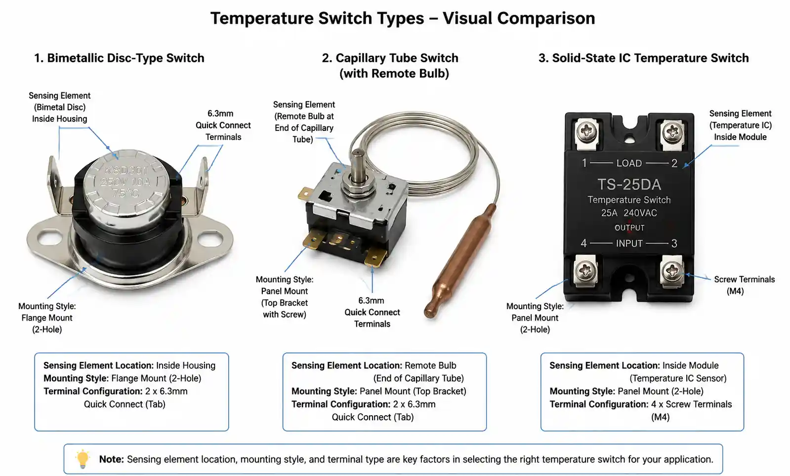
Solid-state switches output low-level signals (3.3V or 5V logic) that cannot directly switch loads. They require external relay or MOSFET driver circuits for power switching. This adds cost and complexity but provides advantages in high-cycle applications (>100K operations), precision control loops, or systems already using logic-level control.
Application-Specific Selection Guide:
For automotive cooling systems (radiator fans, engine protection), use bimetallic or capillary switches rated for 120-130°C setpoint with 10A+ contact rating. Automotive-grade parts must withstand vibration, temperature cycling (-40 to +125°C), and contaminated coolant exposure.
For industrial motor protection, choose bimetallic switches with 10-15°C differential to prevent nuisance trips during load transients. Mount directly on motor housing or windings for fastest thermal response. Manual reset versions ensure operator awareness after overtemperature events.
For HVAC and refrigeration, capillary switches allow remote bulb placement in air ducts or refrigerant lines while keeping switch mechanism in accessible location for maintenance. Setpoint range should cover operating temperatures plus 20% margin.
For battery thermal management in EVs or energy storage, solid-state switches provide the precision and fast response needed to prevent thermal runaway. Use multiple switches at different setpoints for staged cooling response and emergency shutdown.
For hydraulic systems, select switches rated for vibration and with brass or stainless steel wetted parts compatible with hydraulic fluids. Thread-in sensor designs provide better thermal coupling than strap-on types.
4. Wiring Configurations and Circuit Design
Proper wiring configuration is critical for reliable temperature switch operation. Incorrect terminal connections, inadequate wire sizing, or missing protection components lead to premature failure or unsafe operation.
Contact Configuration Basics: Temperature switches are available in three contact configurations: normally open (NO), normally closed (NC), and changeover (SPDT with both NO and NC contacts). A normally open switch has contacts that are open (non-conducting) at temperatures below setpoint and close when temperature rises above setpoint. Normally closed switches operate inversely—contacts are closed below setpoint and open above setpoint.
For protection applications, normally closed contacts are standard. The switch is wired in series with the load or in series with a control circuit coil. If temperature exceeds the safe limit, contacts open and interrupt power. This fail-safe design also protects against switch failure—if the switch mechanism fails or wiring breaks, the circuit opens and prevents damage.
Normally open contacts suit applications where heating or cooling should activate above a threshold temperature, such as radiator fan control or auxiliary heater activation. For critical protection circuits, combine both NO and NC contacts (using SPDT switch) to provide redundant monitoring—NC contact interrupts load while NO contact triggers alarm.
Basic Load Switching Circuit: The simplest configuration connects the temperature switch in series with the load and power source. For a 12V DC cooling fan controlled by a temperature switch, connect positive supply to one switch terminal, the other terminal to fan positive lead, and fan negative to ground. When coolant temperature rises above setpoint, contacts close and fan runs. When temperature drops below (setpoint minus differential), contacts open and fan stops.
This direct-switching approach works for resistive loads up to the switch contact rating. For loads exceeding contact rating or for inductive loads (motors, solenoids), use relay interface. Connect the temperature switch to energize a relay coil rated for the switch contact capacity. The relay power contacts then switch the main load. This protects the temperature switch contacts from high inrush current and arcing.
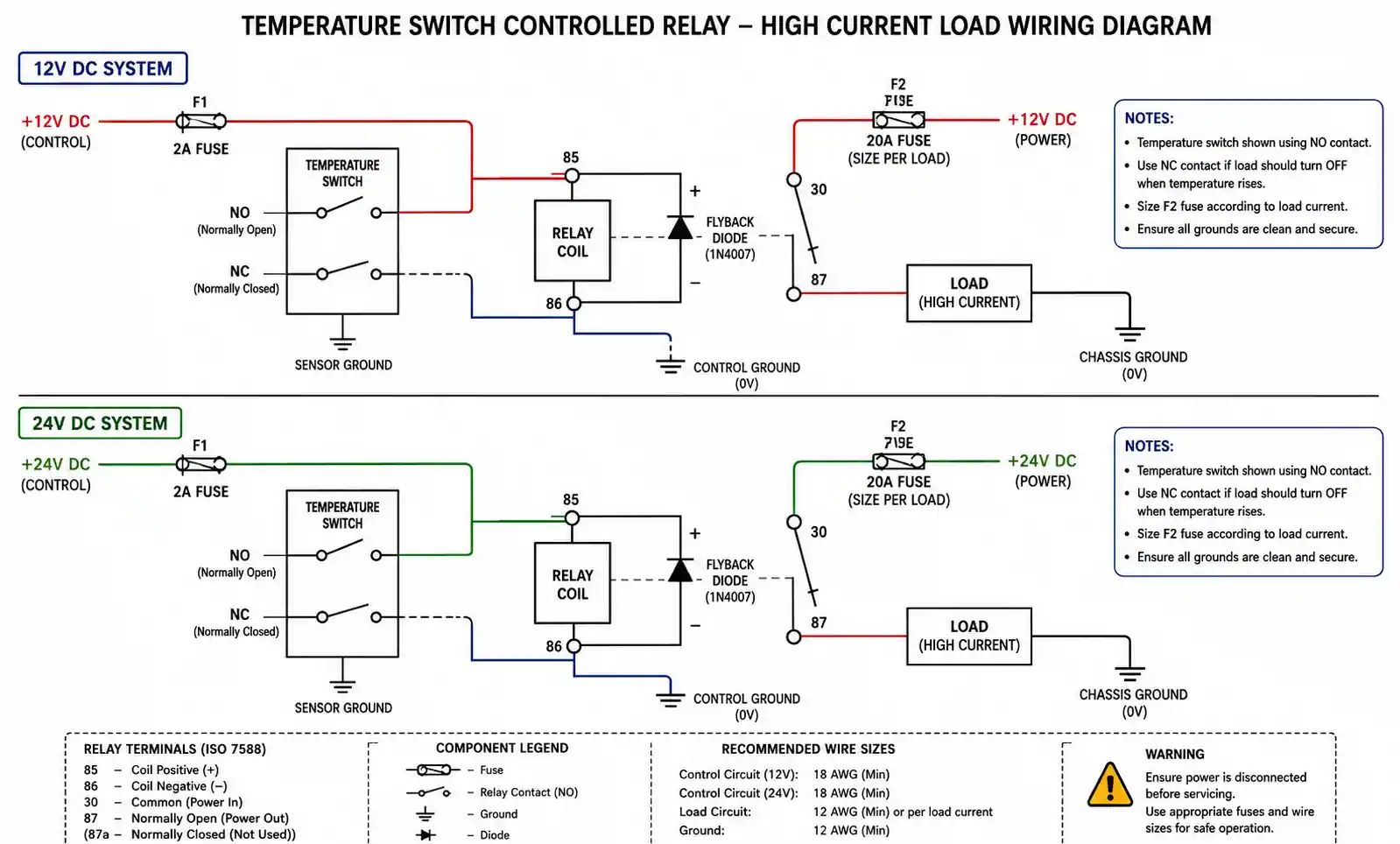
Relay Interface Circuit: For switching high-current loads (>10A) or when the switch is located remotely from the load, use a relay interface. Wire the temperature switch in series with the relay coil and appropriate control voltage (typically 12V or 24V DC). Add a flyback diode (1N4007 or equivalent) across the relay coil with cathode to positive to suppress inductive kickback when contacts open. The relay power contacts switch the main load circuit.
This configuration offers several advantages: the temperature switch only switches low coil current (typically 100-200mA), extending contact life. Multiple loads can be controlled via relay with multiple pole contacts. The relay can be located near the load, minimizing heavy-gauge wiring runs. For automotive applications, use automotive-grade relays rated for vibration and temperature cycling.
Protection Circuit with Alarm and Manual Reset: For critical equipment protection, implement a circuit that both interrupts power and signals an alarm condition. Use an SPDT temperature switch. Connect the NC contact in series with the load to interrupt power when overtemperature occurs. Connect the NO contact to trigger an alarm (buzzer, indicator lamp, or logic input to control system). Add a manual reset button that allows the operator to restart after cooling and fault clearance.
Wire the manual reset button in series with the load and the NC temperature switch contact. After an overtemperature trip, the operator must press and hold (or latch) the reset button to restore operation. This ensures operator awareness and prevents automatic restart into fault conditions. This configuration is required by many industrial safety standards for motor and machinery protection.
Shielded Wiring for Noise Immunity: In electrically noisy environments (near motor drives, switching power supplies, or high-frequency RF sources), use shielded cable for temperature switch wiring. Unshielded wiring can pick up electromagnetic interference that causes false triggering, especially with long wire runs (>5 meters) in the open or near power cables.
Connect shield drain wire to protective earth at one end only (typically at the control panel or relay location) to avoid ground loops. Run signal wiring in separate conduit from power cables. For solid-state temperature switches with logic-level outputs, use twisted pair wiring with shield to minimize common-mode noise. Proper shielding is especially critical in variable frequency drive (VFD) installations where high dv/dt switching generates significant EMI.
Wire Sizing and Voltage Drop: Size wiring according to maximum load current plus 25% safety margin. For long runs, calculate voltage drop to ensure it remains below 3% of supply voltage. A 10A load on 20 meters of 1.5mm² (16 AWG) copper wire drops approximately 2.6V on 12V system—over 20% loss. Use 2.5mm² (14 AWG) minimum for such applications. Voltage drop reduces available power to the load and can prevent proper operation.
For control circuits (relay coils, logic inputs), 0.5-1.0mm² (20-18 AWG) wire typically suffices for runs under 10 meters. Always use wire rated for the maximum ambient temperature along the routing path. In automotive underhood or industrial applications, use wire rated for at least 125°C continuous.
5. Installation Best Practices and Common Mistakes
Proper installation ensures accurate temperature sensing, reliable operation, and long service life. Many field failures result from installation errors rather than component defects. The following best practices reflect common engineering recommendations and field experience from automotive, industrial, and HVAC applications.
Sensor Placement and Thermal Contact: The temperature switch sensing element must be in good thermal contact with the monitored surface, fluid, or air stream. For surface mounting on motor housings, gearboxes, or bearing assemblies, clean the mounting surface thoroughly to remove paint, oxidation, or contamination. Apply a thin layer of thermal compound (similar to that used for semiconductor heat sinks) to improve thermal coupling and reduce response time. Secure the sensor firmly using the provided mounting hardware—loose contact significantly increases thermal resistance.
For immersion in liquids (coolant, hydraulic fluid, lubricating oil), thread the sensor into a boss or fitting that places the sensing element in the flow stream, not in a dead-ended cavity. Stagnant pockets lag the bulk fluid temperature and slow response time. Use thread sealant rated for the fluid and temperature—avoid PTFE tape in high-vibration applications as it can cold-flow and cause leaks. Torque to manufacturer specification to ensure seal without over-stressing the sensor body.
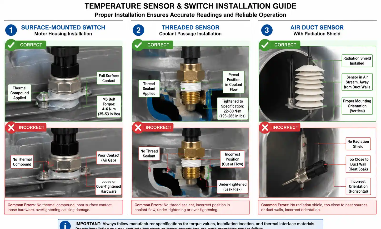
For air temperature sensing in ducts or enclosures, position the sensor away from direct impingement of hot air jets or direct exposure to heating elements. Mount in a location representative of average air temperature. Shield the sensor from radiant heat sources (heating elements, hot surfaces) that can cause false high readings. For ambient air sensing, provide adequate ventilation around the sensor and avoid mounting in sun-exposed enclosures.
Setpoint Calibration and Verification: Never assume the factory setpoint is accurate for your application. Before installation, verify the actual trip point using a controlled heat source and calibrated reference thermometer. Immerse both the temperature switch sensor and reference thermometer in a well-stirred heated fluid bath (water, oil, or glycol depending on temperature range). Slowly increase temperature while monitoring both readings. Note the temperature at which the switch contact changes state and verify it falls within datasheet tolerance.
If adjustment is required and the switch design permits, calibrate according to manufacturer procedures. Some bimetallic switches have adjustable setpoint via screw or cam mechanism. After adjustment, cycle the temperature several times to verify repeatability. Document the actual calibrated setpoint for maintenance records. Setpoint can drift over time, especially in high-cycle applications—plan for periodic recalibration per maintenance schedule.
Common Installation Mistakes to Avoid:
Incorrect contact configuration: Wiring an NC switch where NO is required (or vice versa) results in inverse logic—the load runs when it should be off. Always verify contact state at room temperature before installation. Use a continuity tester to confirm which terminals are connected when cold.
Exceeding contact rating: Switching loads that exceed the rated current or switching inductive loads at full resistive rating causes rapid contact degradation. Contacts weld closed or burn open after a few cycles. Always derate inductive loads by 50% or use relay interface.
Over-torquing threaded sensors: Excessive installation torque cracks ceramic insulators or distorts the bimetallic element, shifting setpoint or causing immediate failure. Use a torque wrench and follow specification. Typical values range from 15-35 N⋅m depending on thread size.
Mounting in high-vibration locations without strain relief: Continuous vibration fatigues wiring connections and can cause intermittent contact. Use vibration-rated terminals or connectors, and provide strain relief within 10 cm of the switch body. In severe vibration environments (engine-mounted sensors), use lockwashers, thread-locking compound, and braided shielded cable.
Inadequate environmental sealing: Moisture ingress into the switch mechanism causes corrosion and contact contamination. Use switches with appropriate IP rating for the environment (IP65 minimum for exposed outdoor or wash-down areas, IP67 for immersion). Seal cable entry points and use waterproof connectors.
Ignoring differential temperature: Installing a switch with 5°C differential in an application with rapid thermal cycling (±2°C) causes continuous contact chatter, reducing electrical life. Match switch differential to application thermal dynamics—wider differential for applications with large thermal mass and slow temperature swings.
Poor wire routing: Running switch wiring parallel to high-current power cables or near ignition coils (in automotive applications) couples electrical noise into the circuit. Maintain at least 15 cm separation from noise sources or use shielded cable. Cross power cables at 90° angles when separation isn't possible.
6. Protection Circuit Design Considerations
Temperature switches serve as the front-line defense against thermal damage in motor, power electronics, battery, and machinery applications. Effective protection circuit design ensures the switch reliably interrupts power before damage occurs while minimizing false trips that disrupt operation.
Contact Protection Networks: When switching inductive loads, the collapsing magnetic field at contact opening generates high voltage spikes (often 10-100× supply voltage) that cause arcing and rapidly erode contacts. An RC snubber network placed across the load suppresses these transients. For DC circuits, connect a resistor (typically 47-100Ω, 1W) in series with capacitor (0.1-1µF, rated for 250V minimum) directly across the inductive load terminals. For AC circuits, use an appropriately rated RC snubber or metal oxide varistor (MOV).
For relay coils controlled by temperature switches, always include a flyback diode (1N4007 or equivalent, rated for at least 2× coil voltage) across the coil with cathode to positive supply. This provides a path for inductive current when the temperature switch opens, preventing voltage spikes that damage switch contacts and nearby electronics.
Redundant Protection Architecture: For critical applications where thermal failure could cause safety hazards or expensive damage (motors, transformers, battery packs, power converters), implement redundant temperature protection. Use two independent temperature switches set at different thresholds. The first switch (warning level) might trigger an alarm or reduce load at 90% of maximum rated temperature. The second switch (trip level) interrupts power at 95-100% of maximum rated temperature.
This staged approach provides advance warning of thermal problems while maintaining operation during transient temperature excursions. It also protects against single-point failure of the protection system. Wire the final trip-level switch in a non-defeatable series circuit so that operator action or control system failure cannot bypass thermal protection.
Alarm and Indication Circuits: A protection circuit should provide clear indication when thermal limits are approached or exceeded. Connect an indicator LED or lamp through a current-limiting resistor to the NO contact of the temperature switch. When temperature exceeds setpoint and the switch trips, the NO contact closes and illuminates the indicator. For systems with centralized monitoring, connect the NO contact to a logic input on a PLC, DCS, or microcontroller for remote alarm annunciation and logging.
In motor control circuits, use the alarm contact to trigger a time-delayed automatic restart after cooling. Implement a timer relay that, after the temperature switch resets (temperature falls below trip point minus differential), waits a programmed delay (typically 5-15 minutes) before allowing restart. This prevents rapid thermal cycling that damages motors and loads. Provide both auto and manual restart modes via selector switch to accommodate different operational requirements.
Ground Fault Protection Integration: In applications where ground faults could cause localized heating (such as motor windings or cable insulation), integrate temperature protection with ground fault detection. If a ground fault current detector trips and the temperature switch also indicates overtemperature, this combination strongly suggests insulation breakdown. The protection logic should lock out restart and require maintenance investigation rather than allowing automatic reset.
Time-Delay and Transient Filtering: Some applications experience brief temperature spikes during normal operation (motor starting, short-term overload, solar heating of enclosures). If these transients are within safe limits but exceed the temperature switch setpoint, they cause nuisance trips. Implement time-delay circuitry that requires temperature to remain above setpoint for a minimum duration (typically 5-60 seconds) before tripping.
A simple time delay can be added using an RC circuit and relay. When the temperature switch closes, it energizes a time-delay relay with adjustable on-delay. The relay output contact controls the final protection action. If temperature returns below setpoint before the timer expires, the circuit resets without tripping. This filters out brief thermal transients while still responding quickly to sustained overtemperature conditions.
For solid-state temperature switch circuits, implement digital filtering in firmware. Sample the switch state at regular intervals (10-100ms) and require a programmed number of consecutive high readings before executing protection action. This provides flexible, adjustable time-delay without additional hardware.
Fail-Safe Design Principles: Protection circuits must default to the safe state (load off) in event of component failure. Use normally closed temperature switch contacts in series with the load so that switch failure, broken wiring, or loss of power opens the circuit. If using relay interface, choose relay with NC contacts for the load circuit. Design control logic so that loss of power to the control circuit de-energizes the load. This "fail-safe" approach ensures that most common failure modes (open circuit, loss of power) result in equipment shutdown rather than loss of protection.
Test the protection circuit periodically by simulating overtemperature conditions (if possible) or by disconnecting the temperature switch to verify load interruption. Document test procedures and results for safety compliance and maintenance tracking.
7. Frequently Asked Questions
What is the difference between normally open (NO) and normally closed (NC) temperature switches?
A normally open switch has contacts that are open (not conducting) when temperature is below the setpoint and close when temperature rises above setpoint. A normally closed switch operates inversely—contacts are closed below setpoint and open above setpoint. For safety and protection circuits, NC configuration is preferred because circuit failure or broken wiring results in open circuit (safe state). Choose NO for control applications like fan activation where you want the load to turn on when temperature rises.
How do I calculate the required differential (deadband) for my application?
Differential should be 2-3× larger than normal temperature fluctuations in your application to prevent contact chatter. For example, if your monitored component temperature varies ±2°C during normal operation, use minimum 5-6°C differential. Also consider thermal mass and response time—systems with large thermal mass (heavy motors, large fluid volumes) can tolerate wider differential without cycling excessively. Narrow differential (<3°C) increases switching frequency and reduces contact life.
Can I use a temperature switch rated for AC voltage in a DC circuit?
Generally yes, but note that contact ratings differ between AC and DC. DC circuits are harder to interrupt because there's no zero-crossing to extinguish the arc. A switch rated for 10A at 250VAC might only handle 5-6A at 24VDC. Always verify the DC rating in the datasheet. For high DC currents (>5A), consider using the temperature switch to control a relay that switches the load.
Why does my temperature switch trip at a different temperature than the setpoint rating?
Several factors cause apparent setpoint deviation. First, verify you're measuring temperature at the same location as the sensor element—thermal gradients in housings or fluids can create 5-10°C differences. Second, check that you're not measuring during dynamic heating or cooling—response time means actual trip occurs after temperature crosses setpoint. Third, setpoint tolerance (typically ±3-5°C) is normal. Finally, aging, contact contamination, or mechanical damage can shift setpoint—replace if deviation exceeds specification.
What type of temperature switch is best for automotive applications?
Automotive applications require switches that withstand vibration, thermal cycling (-40 to +125°C ambient), contaminated fluids, and electromagnetic interference. Bimetallic or capillary switches with threaded brass bodies and automotive-grade terminals are standard. Look for parts meeting automotive specifications such as AEC-Q200 for components or equivalent OEM requirements. Contact ratings should be at least 10A for direct fan switching, 3-5A for relay coil control. Choose normally closed configuration for engine overtemperature protection.
How often should temperature switches be tested or replaced?
For critical protection applications, test annually by simulating overtemperature conditions (if feasible) or by injecting calibrated heat and verifying trip point. For less critical applications, test during equipment maintenance intervals. Replace switches if setpoint drift exceeds ±10°C from nominal, contacts show burning or pitting, housing is cracked, or after 100,000+ electrical switching cycles. Mechanical-only operation (dry cycling with no load) doesn't significantly age contacts—electrical life is the limiting factor.
Can I adjust the setpoint of a fixed-setpoint temperature switch?
Most industrial bimetallic switches have limited adjustment capability via calibration screw or adjustable stop, typically allowing ±5-10°C from nominal setpoint. Capillary switches are generally non-adjustable. Solid-state switches with digital configuration may offer wide setpoint adjustment. Never attempt to "bend" or mechanically modify bimetallic elements—this causes unpredictable setpoint shift and reduced reliability. If your application requires a setpoint more than 10°C from available standard values, specify a custom setpoint from the manufacturer or choose a different switch model.
What causes temperature switch contacts to fail, and how can I prevent it?
Contact failure mechanisms include welding (contacts stick closed from high inrush current), erosion (material transfer from arc damage), contamination (oil, moisture, or oxidation increasing contact resistance), and mechanical fatigue (spring weakening from excessive cycling). Prevention strategies: derate contact current to 50% of rating for inductive loads, use RC snubber networks across inductive loads, add relay interface for high-current loads, seal switch from contaminants using IP65+ rated housing, choose gold-plated contacts for low-voltage logic-level switching, and match switch differential to application to avoid excessive cycling.
8. Conclusion and Next Steps
Temperature switches provide cost-effective, reliable thermal protection when properly selected and installed. The key decision points are choosing the right sensing technology (bimetallic for rugged cost-sensitive applications, capillary for remote sensing, solid-state for precision), matching contact rating and configuration to your load, and ensuring proper installation with good thermal coupling and appropriate wiring protection.
For motor and machinery protection, prioritize bimetallic switches with adequate contact rating and differential to prevent nuisance trips. For automotive cooling systems, specify automotive-grade parts with vibration and contamination resistance. For precision applications like battery thermal management, solid-state switches with relay interface provide the accuracy and fast response required.
Before finalizing your design, verify the actual trip point with calibrated test equipment, implement appropriate contact protection for inductive loads, and design your protection circuit with fail-safe principles. For critical applications, consider redundant temperature monitoring with staged alarms and trip levels.