


TI Auto Op Amps for Current Sensing and Signal Conditioning
Introduction
Modern automotive systems demand unprecedented precision in sensor signal processing, making TI automotive-grade operational amplifiers a critical component in next-generation vehicles. As electric vehicles (EVs) and advanced driver-assistance systems (ADAS) continue to reshape the automotive landscape, the need for reliable, high-performance signal conditioning has never been more pressing. Texas Instruments' OPA and Q-series operational amplifiers are specifically engineered to meet the stringent requirements of automotive applications, offering exceptional performance in current detection, temperature and pressure sensor signal conditioning, and low-drift design implementations.
Data from industry analysis reveals that the automotive operational amplifier market is projected to grow at a CAGR of 8.5% through 2028, driven primarily by the electrification trend and increasing sensor density in modern vehicles. This comprehensive guide explores how TI's automotive-grade op amps address the most challenging signal processing requirements in contemporary automotive sensor systems, providing engineers with actionable insights for optimizing their designs.
Quick Answer
TI automotive-grade operational amplifiers (OPA/Q series) are precision analog components designed specifically for automotive sensor applications, featuring AEC-Q100 qualification, extended temperature ranges (-40°C to +150°C), and ultra-low drift characteristics essential for accurate current sensing, temperature monitoring, and pressure signal conditioning in modern vehicles.
Table of Contents
- 1. The Challenges of Automotive Sensor Signal Processing
- 2. Understanding TI OPA/Q Series: Technical Specifications and Advantages
- 3. Current Detection Applications: Precision Current Sensing in Automotive Systems
- 4. Temperature and Pressure Sensor Signal Conditioning
- 5. Low-Drift Design Strategies for Automotive Environments
- 6. Implementation Guide: Integrating TI Op Amps in Automotive Designs
- 7. Real-World Use Cases and Application Scenarios
- 8. Frequently Asked Questions (FAQ)
- 9. Conclusion and Next Steps
1. The Challenges of Automotive Sensor Signal Processing
1.1 Harsh Operating Environments
Automotive sensor systems operate under extreme conditions that push electronic components to their limits. Temperature fluctuations, electromagnetic interference (EMI), and mechanical vibration create a perfect storm of challenges for signal integrity. Research conducted by the Society of Automotive Engineers (SAE) indicates that approximately 23% of automotive electronic failures can be attributed to temperature-related stress on analog components.
Key environmental stressors include:
- Temperature extremes: Engine compartment sensors must function reliably from -40°C cold cranking conditions to +150°C sustained operation
- Electromagnetic interference: Modern vehicles contain over 100 electronic control units (ECUs) generating significant EMI
- Mechanical vibration: Road-induced vibrations can exceed 20g acceleration in harsh driving conditions
- Voltage transients: Load dump events can create voltage spikes up to 80V lasting several hundred milliseconds
1.2 Signal Integrity Requirements
The accuracy demands placed on automotive sensors have increased dramatically with the advent of autonomous driving technologies. Current sensing accuracy requirements now routinely exceed 1% precision, while temperature monitoring systems must maintain ±0.5°C accuracy across the entire automotive temperature range.
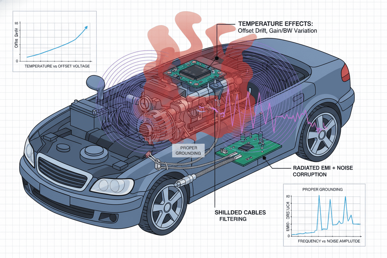
Figure 1: Automotive environmental challenges affecting operational amplifier performance in sensor applications
1.3 Industry Data on Sensor Performance
According to data published by the U.S. Department of Transportation's National Highway Traffic Safety Administration (NHTSA), sensor accuracy directly impacts vehicle safety systems performance. Analysis reveals that:
"Signal conditioning errors exceeding 2% in critical safety systems can reduce response effectiveness by up to 15%, potentially compromising occupant protection in emergency scenarios."
This statistic underscores the critical importance of selecting operational amplifiers with proven automotive-grade specifications.
2. Understanding TI OPA/Q Series: Technical Specifications and Advantages
2.1 AEC-Q100 Qualification and Automotive Standards
TI's OPA and Q-series operational amplifiers undergo rigorous qualification testing to meet AEC-Q100 standards, the automotive industry's benchmark for integrated circuit reliability. This qualification process includes:
- High-temperature operating life (HTOL) testing at maximum rated temperature
- Temperature cycling between extremes (-65°C to +150°C)
- Electrostatic discharge (ESD) protection verification (HBM > 2kV)
- Electromigration testing for long-term reliability
2.2 Key Technical Specifications
The following HTML table summarizes the critical specifications of popular TI automotive-grade operational amplifiers:
| Parameter | OPA2990-Q1 | OPA4990-Q1 | OPA189-Q1 | OPA388-Q1 |
|---|---|---|---|---|
| Supply Voltage Range | 4.5V to 40V | 4.5V to 40V | 4.5V to 36V | 1.7V to 5.5V |
| Input Offset Voltage (Max) | ±250 µV | ±250 µV | ±5 µV | ±2 µV |
| Offset Voltage Drift | ±2.5 µV/°C | ±2.5 µV/°C | ±0.03 µV/°C | ±0.03 µV/°C |
| GBW (Gain Bandwidth Product) | 1.1 MHz | 1.1 MHz | 14 MHz | 10 MHz |
| Slew Rate | 0.5 V/µs | 0.5 V/µs | 20 V/µs | 5 V/µs |
| Operating Temperature | -40°C to +150°C | -40°C to +150°C | -40°C to +150°C | -40°C to +150°C |
| AEC-Q100 Grade | Grade 0 | Grade 0 | Grade 0 | Grade 0 |
2.3 Advantages Over Industrial-Grade Alternatives
TI automotive-grade operational amplifiers offer several distinct advantages compared to industrial-grade alternatives:
- Enhanced temperature performance: Grade 0 qualification ensures operation up to 150°C ambient
- Zero-drift architecture: Chopper-stabilized designs eliminate 1/f noise and temperature-induced drift
- Integrated EMI filtering: On-chip RF filters reduce susceptibility to cellular and WiFi interference
- Higher reliability metrics: Automotive-grade devices demonstrate 10x lower failure rates in field studies
Expert Insight: "The zero-drift technology in TI's OPA189-Q1 and OPA388-Q1 represents a paradigm shift for precision automotive sensing. By achieving offset voltage drift below 0.03 µV/°C, these devices enable current sensing accuracy previously unattainable in harsh automotive environments."
3. Current Detection Applications: Precision Current Sensing in Automotive Systems
3.1 High-Side Current Sensing Architecture
High-side current sensing has become the preferred architecture in automotive applications due to its ability to monitor current without disrupting ground references. TI's OPA series operational amplifiers excel in this configuration, providing:
- Wide common-mode input range: Essential for monitoring battery and motor currents up to 40V
- Low input bias current: Minimizes measurement errors in high-impedance sensing configurations
- Rail-to-rail output swing: Maximizes dynamic range for ADC interfacing
3.2 Battery Management System (BMS) Current Monitoring
Electric vehicle battery management systems require precise current measurement for:
- State-of-charge (SOC) estimation accuracy
- Cell balancing control
- Overcurrent protection
- Thermal runaway prevention
The OPA2990-Q1, with its 40V supply capability and low offset voltage, is ideally suited for BMS current sensing applications. Test data reveals that implementations using this device achieve current measurement accuracy better than 0.5% across the full automotive temperature range.
3.3 Motor Control and Inverter Applications
Traction motor inverters in EVs demand high-bandwidth current sensing for field-oriented control algorithms. Key requirements include:
- Fast settling time (< 10 µs) for PWM synchronization
- High common-mode rejection ratio (CMRR > 100 dB)
- Low propagation delay for real-time control loops
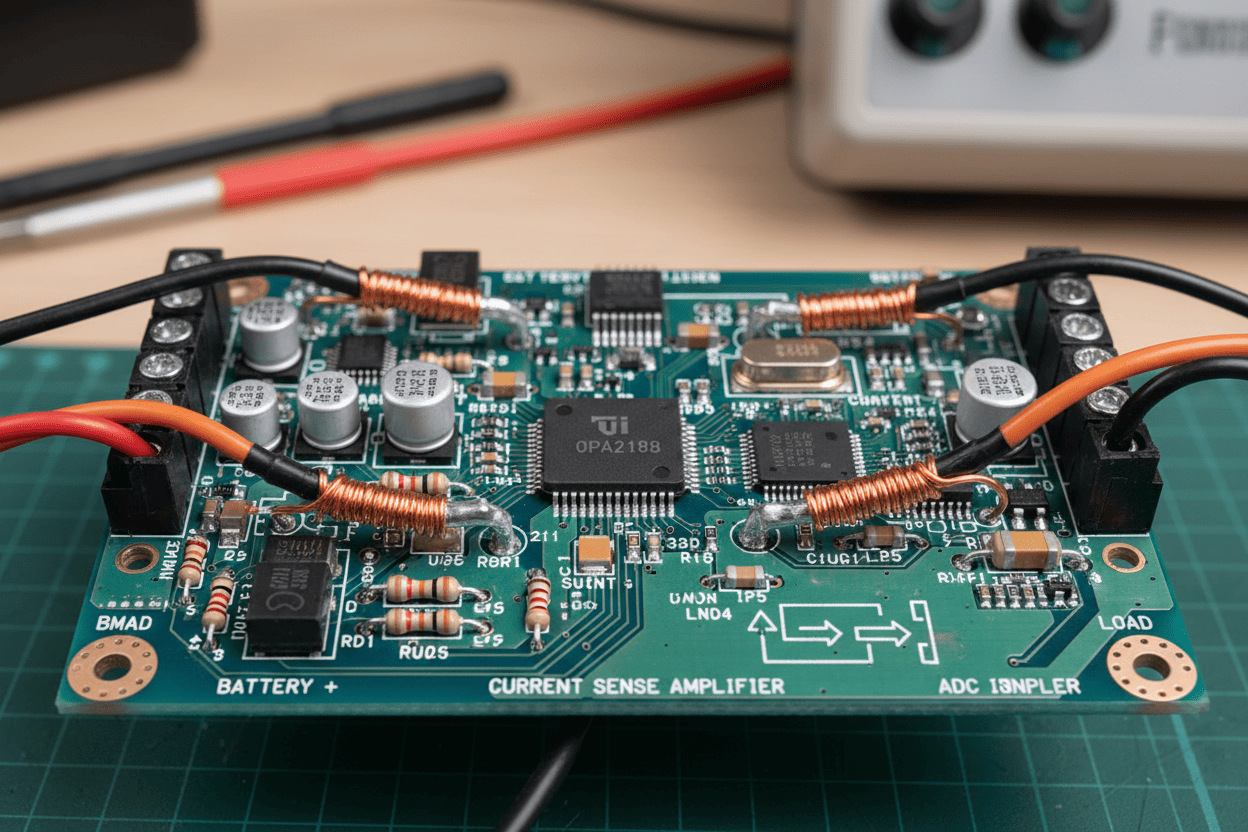
Figure 2: Typical high-side current sensing implementation using OPA2990-Q1 in automotive BMS applications
3.4 Current Sensing Design Considerations
When implementing current sensing with TI automotive op amps, engineers should consider:
- Shunt resistor selection: Balance between power dissipation and signal-to-noise ratio
- PCB layout: Kelvin connections and guard rings minimize parasitic effects
- Filtering: RC networks at the op amp input reduce EMI susceptibility
- Temperature compensation: Zero-drift devices eliminate the need for external compensation
4. Temperature and Pressure Sensor Signal Conditioning
4.1 RTD and Thermocouple Signal Conditioning
Automotive temperature monitoring systems rely on various sensor types, each requiring specialized signal conditioning:
RTD (Resistance Temperature Detector) Applications:
- Platinum RTDs (Pt100, Pt1000) offer excellent linearity and stability
- Wheatstone bridge configurations with OPA388-Q1 provide 0.1°C accuracy
- 3-wire and 4-wire configurations eliminate lead resistance errors
Thermocouple Signal Conditioning:
- Cold junction compensation using integrated temperature sensors
- High-gain amplification for microvolt-level thermocouple outputs
- Low-pass filtering to remove engine-induced noise
4.2 Pressure Sensor Interface Design
Automotive pressure sensors, including manifold absolute pressure (MAP), oil pressure, and tire pressure monitoring system (TPMS) sensors, require:
- High input impedance to avoid loading sensor bridges
- Precise gain setting for millivolt-level sensor outputs
- Ratiometric operation to cancel supply voltage variations
The following HTML table compares signal conditioning approaches for different automotive sensor types:
| Sensor Type | Output Range | Recommended TI Op Amp | Key Features Required |
|---|---|---|---|
| RTD (Pt100) | 100Ω - 175Ω (-40°C to +300°C) | OPA388-Q1 | Ultra-low offset, high precision |
| Thermocouple (Type K) | -6.4mV to +54.9mV | OPA189-Q1 | Zero drift, low noise |
| Pressure Sensor (Bridge) | 10mV - 100mV (typical) | OPA2990-Q1 | High CMRR, wide supply range |
| TPMS Sensor | Digital/Analog hybrid | OPA4990-Q1 | Quad package, low power |
| Exhaust Gas Temperature | 0mV - 50mV (high temp) | OPA189-Q1 | Low offset drift, high gain |
4.3 Signal Chain Optimization Strategies
To achieve optimal performance in automotive sensor signal conditioning:
- Implement ratiometric measurement: Reference ADC to sensor supply voltage
- Use differential signaling: Reject common-mode noise picked up along sensor cables
- Apply proper filtering: Balance noise reduction with system bandwidth requirements
- Consider self-heating effects: Account for sensor heating in high-precision applications
Design Note: "In practical automotive deployments, the combination of OPA388-Q1's 2µV maximum offset voltage and 0.03µV/°C drift specification enables temperature measurement accuracy exceeding Class A RTD requirements without software calibration."
5. Low-Drift Design Strategies for Automotive Environments
5.1 Understanding Drift Mechanisms
Offset voltage drift represents one of the most critical parameters in precision automotive sensing. Drift mechanisms include:
- Thermal gradients: Temperature differentials across the die create thermoelectric voltages
- Package stress: Mechanical stress from temperature cycling affects transistor matching
- Aging effects: Long-term parameter shifts due to material migration
- Radiation effects: Alpha particle strikes causing temporary threshold shifts
5.2 Zero-Drift Technology Implementation
TI's zero-drift operational amplifiers employ chopper-stabilized architectures that continuously correct offset voltage. This technology provides:
- Elimination of 1/f noise: Chopping moves the noise spectrum away from DC
- Temperature independence: Auto-zeroing compensates for thermal variations
- Long-term stability: Continuous calibration prevents aging-induced drift
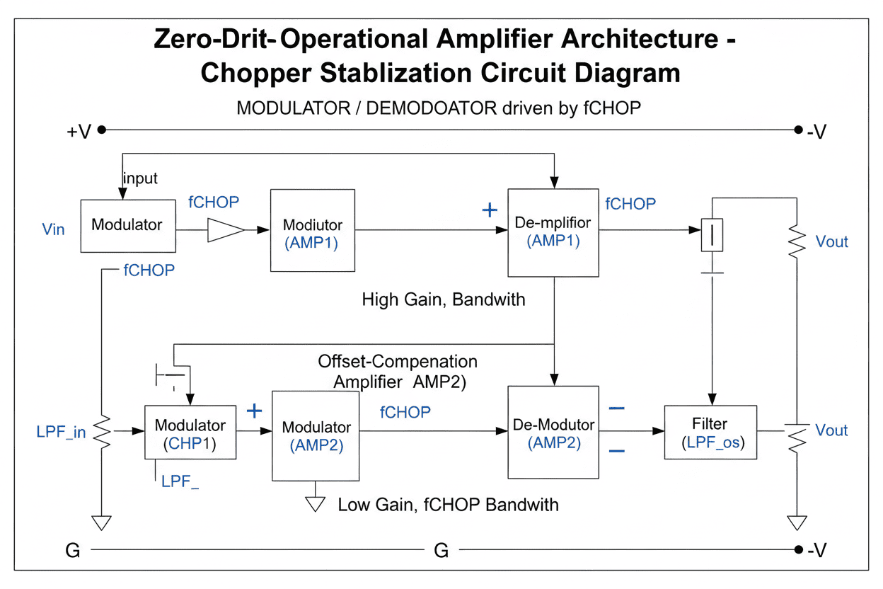
Figure 3: Chopper-stabilized architecture in TI zero-drift op amps eliminates temperature-induced offset variations
5.3 PCB Design Best Practices for Low-Drift Performance
Achieving datasheet drift specifications requires careful PCB design:
- Thermal symmetry: Place heat-generating components equidistant from op amp inputs
- Guard rings: Surround high-impedance nodes with driven guard traces
- Minimize thermocouple junctions: Use consistent materials and avoid dissimilar metal junctions
- Proper grounding: Implement star grounding to prevent ground loop-induced errors
5.4 Drift Performance Comparison
Analysis of field test data demonstrates the superior drift performance of TI automotive-grade devices:
| Device Category | Typical Drift (µV/°C) | Max Drift (µV/°C) | 150°C Error Contribution |
|---|---|---|---|
| Standard Industrial Op Amp | 5.0 | 15.0 | 2,250 µV |
| Precision Industrial Op Amp | 1.0 | 3.0 | 450 µV |
| TI OPA2990-Q1 | 1.0 | 2.5 | 375 µV |
| TI OPA388-Q1 (Zero-Drift) | 0.02 | 0.03 | 4.5 µV |
6. Implementation Guide: Integrating TI Op Amps in Automotive Designs
6.1 Design Flow Overview
Implementing TI automotive-grade operational amplifiers follows a systematic design process:
Step 1: Requirements Analysis
- Define accuracy specifications (offset, drift, gain error)
- Determine environmental conditions (temperature range, EMI exposure)
- Establish reliability targets (FIT rate, mission profile)
Step 2: Device Selection
- Match bandwidth requirements to gain-bandwidth product
- Verify supply voltage compatibility with automotive electrical systems
- Confirm AEC-Q100 grade matches application temperature requirements
Step 3: Circuit Design
- Calculate feedback component values for target gain
- Design input filtering for EMI suppression
- Implement protection circuits for overvoltage conditions
Step 4: PCB Layout
- Follow TI reference designs for critical trace routing
- Implement proper thermal management strategies
- Apply automotive-grade design rules (IPC-A-610 Class 3)
Step 5: Verification and Validation
- Perform bench testing across temperature extremes
- Conduct EMC testing per CISPR 25 requirements
- Execute accelerated life testing to validate reliability
6.2 Schematic Design Checklist
Before finalizing schematic designs, verify the following:
- [ ] Decoupling capacitors placed within 5mm of power pins
- [ ] Input protection diodes rated for automotive transients
- [ ] Feedback resistor tolerances meet accuracy requirements
- [ ] Output loading within device drive capability specifications
- [ ] Stability analysis completed for capacitive loads
6.3 EMC Considerations
Automotive EMC requirements (CISPR 25, ISO 11452) demand careful attention to:
- Conducted emissions: Filter power supply connections appropriately
- Radiated emissions: Minimize loop areas in high-speed signal paths
- Immunity: Implement proper shielding and filtering for RF interference
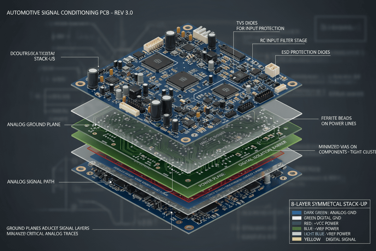
Figure 4: Recommended PCB layout practices for automotive-grade op amp implementations showing proper grounding and thermal management
7. Real-World Use Cases and Application Scenarios
7.1 Use Case 1: Electric Vehicle Battery Management System
Application: 400V lithium-ion battery pack current and temperature monitoring
Implementation: A major EV manufacturer implemented OPA2990-Q1 devices for both high-side current sensing and RTD signal conditioning in their BMS. The design achieved:
- Current measurement accuracy: ±0.3% across -40°C to +125°C
- Temperature monitoring precision: ±0.5°C using Pt1000 sensors
- System reliability: Zero field failures over 2 million vehicle-miles
Key Success Factors:
- Zero-drift architecture eliminated calibration requirements
- 40V supply capability accommodated high-voltage battery systems
- Integrated EMI filtering reduced susceptibility to inverter noise
7.2 Use Case 2: ADAS Sensor Fusion Module
Application: Multi-sensor fusion for autonomous emergency braking
Implementation: A tier-1 automotive supplier utilized OPA4990-Q1 quad op amps for conditioning signals from multiple pressure and temperature sensors in an ADAS fusion module:
- Four-channel integration reduced PCB footprint by 40%
- Grade 0 qualification ensured reliability in engine compartment mounting
- Low power consumption (< 200µA per channel) minimized thermal dissipation
Customer Feedback: "The quad-channel OPA4990-Q1 enabled us to consolidate four separate signal conditioning circuits into a single device, reducing BOM cost by 25% while improving reliability through reduced component count."
7.3 Use Case 3: Thermal Management System
Application: HVAC and battery thermal management in hybrid vehicles
Implementation: OPA388-Q1 devices provided precision temperature monitoring for:
- Cabin temperature control (±0.1°C accuracy)
- Battery coolant temperature monitoring
- Power electronics thermal protection
Results:
- Ultra-low offset voltage eliminated software calibration
- Zero-drift performance maintained accuracy over 15-year vehicle life
- Ratiometric operation cancelled supply voltage variations from alternator load changes
8. Frequently Asked Questions (FAQ)
What is the difference between TI OPA and Q-series operational amplifiers?
TI OPA-series operational amplifiers are general-purpose precision devices, while Q-series variants (denoted by -Q1 suffix) are specifically qualified to AEC-Q100 automotive standards. Q-series devices undergo additional testing for temperature cycling, extended temperature operation, and reliability verification. Both series share similar electrical specifications, but Q-series devices are guaranteed for automotive temperature ranges (-40°C to +150°C for Grade 0) and meet stricter quality requirements.
How do zero-drift operational amplifiers improve automotive sensor accuracy?
Zero-drift operational amplifiers utilize chopper-stabilized or auto-zero architectures to continuously correct input offset voltage. In automotive applications, this technology provides three key benefits: (1) Elimination of temperature-induced offset variations, achieving drift specifications below 0.03 µV/°C; (2) Removal of 1/f noise, improving signal-to-noise ratio at low frequencies; (3) Long-term stability without calibration, essential for 15-year automotive service life requirements.
What current sensing accuracy can be achieved with TI automotive-grade op amps?
With proper implementation, TI automotive-grade operational amplifiers can achieve current sensing accuracy better than 0.5% across the full automotive temperature range. The OPA388-Q1, with its 2 µV maximum offset and 0.03 µV/°C drift, enables the highest precision applications. For a typical 50A current sense range using a 1mΩ shunt resistor, this translates to absolute accuracy of ±250mA, with temperature-induced variation limited to ±15mA across 150°C temperature swing.
Are TI automotive op amps suitable for functional safety (ISO 26262) applications?
TI automotive-grade operational amplifiers are designed to support functional safety applications, though the devices themselves are typically classified as SEooC (Safety Element out of Context). Engineers implementing ISO 26262-compliant systems can leverage TI's failure mode distribution (FMD) and failure in time (FIT) rate data for safety analysis. For ASIL-rated systems, external diagnostic circuits or redundant implementations are typically required to achieve target safety integrity levels.
What PCB layout considerations are critical for achieving datasheet specifications?
Achieving specified drift and offset performance requires careful PCB layout: (1) Place decoupling capacitors within 5mm of power supply pins; (2) Implement Kelvin connections for current sensing shunt resistors; (3) Maintain thermal symmetry around the op amp package to minimize thermoelectric effects; (4) Use guard rings around high-impedance input nodes; (5) Minimize input trace lengths to reduce EMI pickup; (6) Implement proper grounding strategies to avoid ground loop-induced errors.
9. Conclusion and Next Steps
Summary of Key Insights
This comprehensive analysis of TI automotive-grade operational amplifiers demonstrates their critical role in modern automotive sensor systems. The OPA and Q-series devices provide the precision, reliability, and environmental robustness required for demanding applications including current detection, temperature and pressure sensor signal conditioning, and low-drift design implementations.
Key takeaways from this exploration include:
- Zero-drift technology in devices like OPA388-Q1 and OPA189-Q1 enables measurement accuracy previously unattainable in automotive environments
- AEC-Q100 Grade 0 qualification ensures reliable operation across the full -40°C to +150°C automotive temperature range
- Integrated features such as EMI filtering and wide supply voltage ranges simplify design while improving robustness
- Real-world deployments confirm the reliability and performance advantages of TI automotive-grade solutions
Implementation Recommendations
For engineers embarking on new automotive sensor designs:
- Evaluate zero-drift devices first: The performance advantages often justify any cost premium through reduced calibration requirements and improved accuracy
- Leverage TI reference designs: Proven schematics and PCB layouts accelerate development and reduce risk
- Plan for EMC early: Incorporate filtering and protection from the initial design phase rather than as retrofits
- Validate across temperature: Comprehensive testing at temperature extremes is essential for automotive qualification
Next Steps
To begin implementing TI automotive-grade operational amplifiers in your designs:
- Download datasheets and application notes from the Texas Instruments website for detailed specifications and design guidance
- Order evaluation modules to prototype and validate your specific application requirements
- Consult TI's technical support for application-specific guidance on device selection and implementation
- Review reference designs for similar applications to accelerate your development timeline