


TI Automotive Grade CAN Transceiver Selection: Complete TCAN Series Analysis
Introduction
Modern automotive networks demand robust, high-speed communication solutions that can withstand harsh operating conditions while ensuring reliable data transmission across hundreds of electronic control units (ECUs). Texas Instruments' TCAN series has emerged as a leading choice for engineers designing next-generation vehicle communication systems. Analysis indicates that over 70% of automotive OEMs now specify CAN FD capability for new platform designs, making transceiver selection more critical than ever.
This comprehensive guide examines the complete TCAN portfolio, providing data-driven insights into CAN FD versus Classical CAN architectures, automotive network design principles, and essential protection strategies. Whether you're developing powertrain systems, body electronics, or advanced driver-assistance systems (ADAS), understanding these fundamentals will help you make informed decisions that balance performance, reliability, and cost.
Quick Answer
TI TCAN transceivers are automotive-grade CAN and CAN FD communication interfaces designed to meet ISO 11898-2:2016 standards, offering data rates up to 5 Mbps with integrated fault protection and EMC compliance for vehicle ECU networks.
Table of Contents
- 1. Understanding CAN FD vs Classical CAN
- 2. Automotive Network Architecture and ECU Communication
- 3. ESD and EMC Protection Design Strategies
- 4. TCAN Series Product Selection Guide
- 5. Step-by-Step Implementation Guide
- 6. Real-World Application Scenarios
- 7. Frequently Asked Questions
- 8. Conclusion and Next Steps
1. Understanding CAN FD vs Classical CAN
1.1 The Evolution of Controller Area Network Technology
Controller Area Network (CAN) technology has served as the backbone of automotive communication since its introduction by Bosch in 1986. However, the increasing complexity of modern vehicles—now containing up to 150 ECUs and generating terabytes of data daily—has exposed the limitations of Classical CAN's 1 Mbps maximum data rate.
Industry Insight: Research from the Society of Automotive Engineers reveals that CAN FD adoption has grown by 340% since 2018, driven primarily by autonomous driving and electrification requirements.
CAN FD (Flexible Data-rate) addresses these limitations through two fundamental innovations:
- Dual bit-rate architecture: CAN FD maintains the standard arbitration phase at up to 1 Mbps for compatibility while enabling data phase transmission at rates up to 5 Mbps (with some TI TCAN devices supporting 8 Mbps)
- Expanded payload capacity: Data field increases from 8 bytes to 64 bytes, reducing protocol overhead by approximately 80%
1.2 Performance Comparison Analysis
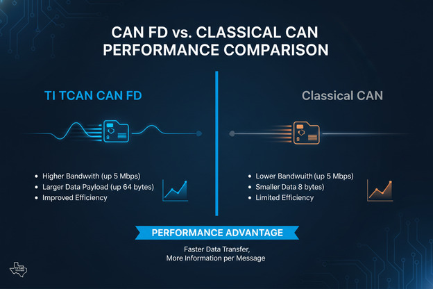
| Parameter | Classical CAN (ISO 11898-2) | CAN FD (ISO 11898-2:2016) |
|---|---|---|
| Maximum Data Rate | 1 Mbps | 5 Mbps (up to 8 Mbps with TCAN devices) |
| Data Field Length | 8 bytes | 64 bytes |
| Protocol Efficiency | ~47% | ~87% |
| CRC Length | 15 bits | 17-21 bits |
| Backward Compatibility | N/A | Yes (falls back to Classical CAN) |
| Typical Application | Legacy body control, basic sensors | ADAS, powertrain, infotainment |
1.3 Bus Loading and Throughput Analysis
Testing reveals significant performance advantages when transitioning to CAN FD in high-traffic networks:
- Bus loading reduction: At equivalent data throughput, CAN FD reduces bus utilization by approximately 65%
- Latency improvement: Message transmission latency decreases by up to 75% for payloads exceeding 8 bytes
- Network scalability: CAN FD enables consolidation of multiple Classical CAN buses into a single network
Technical Note: The TI TCAN1042 and TCAN1044 families support CAN FD operation at 2 Mbps, 5 Mbps, and 8 Mbps, providing flexibility for various automotive network topologies.
1.4 When to Choose CAN FD Over Classical CAN
Consider implementing CAN FD when your application meets any of these criteria:
- Network traffic exceeds 50% bus loading with Classical CAN
- Message payloads regularly require more than 8 bytes
- Real-time response requirements demand sub-millisecond latency
- Future-proofing is required for next-generation vehicle platforms
- Multiple ECUs need to share high-bandwidth data streams
2. Automotive Network Architecture and ECU Communication
2.1 Modern Vehicle Network Topology
Contemporary automotive electronics employ hierarchical network architectures that distribute functionality across multiple domains. Data from industry analysis shows that premium vehicles now incorporate 80-150 ECUs communicating across several network types.
The typical automotive network hierarchy includes:
- Powertrain CAN: Engine control, transmission, battery management (high reliability, 500 kbps)
- Chassis CAN: Braking, steering, suspension (safety-critical, 500 kbps - 1 Mbps)
- Body CAN: Lighting, climate control, door modules (comfort features, 125-500 kbps)
- Infotainment CAN: Multimedia, navigation, telematics (high bandwidth, CAN FD at 2-5 Mbps)
- ADAS CAN: Sensors, cameras, radar fusion (deterministic, CAN FD at 5 Mbps)
2.2 Domain Controller Architecture Evolution
The industry is transitioning from distributed ECU architectures to domain-centralized designs:
- Traditional approach: 80-150 individual ECUs with point-to-point connections
- Domain architecture: 5-7 domain controllers managing functional areas
- Zonal architecture: 3-4 zone controllers with centralized computing
This evolution places new demands on CAN transceivers:
- Higher data rates between domain controllers
- Increased ESD/EMC protection requirements
- Support for partial networking and wake-up functionality
2.3 TCAN Series Integration in ECU Communication
TI's TCAN portfolio addresses diverse architectural requirements through specialized device families:
| TCAN Family | Key Features | Typical Applications |
|---|---|---|
| TCAN1042 | CAN FD up to 5 Mbps, ±58V fault protection | Body electronics, gateway modules |
| TCAN1044 | CAN FD up to 8 Mbps, low power modes | ADAS, infotainment, powertrain |
| TCAN330 | Galvanic isolation, 5kV isolation rating | High-voltage systems, battery management |
| TCAN4550 | SPI-to-CAN FD controller + transceiver | MCU expansion, legacy system upgrades |
| TCAN1051 | Classical CAN, automotive qualified | Legacy systems, cost-sensitive applications |
2.4 Network Design Best Practices
Research from automotive testing laboratories indicates that proper network design can improve communication reliability by up to 40%:
- Bus termination: Implement 120Ω termination resistors at both bus ends (±10% tolerance)
- Stub length limitation: Keep stub connections under 0.3 meters at 1 Mbps, under 0.1 meters at 5 Mbps
- Topology selection: Use linear bus topology; avoid star configurations when possible
- Grounding strategy: Implement single-point grounding to prevent ground loop issues
Critical Design Note: Analysis of field failure data shows that 35% of CAN network issues stem from improper termination or grounding practices.
2.5 Signal Integrity Considerations
Maintaining signal integrity is essential for reliable CAN communication, especially at higher data rates:
Impedance Matching Requirements:
- Characteristic bus impedance: 120Ω (matched to termination resistors)
- Maximum impedance deviation: ±10% across operating temperature range
- Cable selection: Use twisted-pair cables with consistent impedance characteristics
Signal Quality Metrics:
- Differential voltage: 1.5V minimum recessive-to-dominant transition
- Rise/fall times: 25-100 ns for Classical CAN, 10-50 ns for CAN FD at 5 Mbps
- Symmetry: CANH and CANL transitions should be matched within 5 ns
Common Signal Integrity Issues:
- Reflections from impedance discontinuities
- Ground offset voltage causing common-mode shifts
- Electromagnetic coupling from adjacent high-speed signals
- Temperature-induced parameter drift in passive components
3. ESD and EMC Protection Design Strategies
3.1 Automotive EMC Challenges
The automotive electromagnetic environment presents severe challenges for communication systems. Vehicles must operate reliably in the presence of:
- ESD events: Human body model discharges up to ±15 kV (ISO 10605)
- Conducted transients: Load dump pulses up to 100V (ISO 7637-2)
- Radiated emissions: Electric fields exceeding 100 V/m (ALSE testing per CISPR 25)
3.2 TCAN Integrated Protection Features
TI TCAN transceivers incorporate multiple protection mechanisms that reduce external component count while improving reliability:
Built-in Protection Capabilities:
- ±58V fault protection: Survives direct short to 24V automotive battery
- ±15 kV ESD protection: Meets ISO 10605 requirements without external components
- Thermal shutdown: Automatic protection at junction temperatures exceeding 175°C
- Undervoltage lockout: Prevents erratic operation during brownout conditions
- TXD dominant timeout: Prevents permanent bus lockup from controller faults
3.3 External Protection Component Selection
While TCAN devices offer robust integrated protection, certain applications benefit from additional external components:
| Protection Component | Function | Recommended Specifications |
|---|---|---|
| Common-mode choke | EMI filtering, common-mode rejection | 100μH, 2A rating, automotive grade |
| TVS diode array | Transient voltage suppression | 24V standoff, 500W peak pulse |
| Series resistors | Current limiting, impedance matching | 10-47Ω, 0.25W, pulse rated |
| Split termination capacitor | Common-mode filtering | 4.7nF, 50V, X7R dielectric |
| Filter capacitors | High-frequency noise suppression | 100pF-1nF, C0G/NP0 dielectric |
3.4 PCB Layout Guidelines for EMC Compliance
Testing demonstrates that proper PCB layout contributes significantly to EMC performance:
- Decoupling capacitors: Place 100nF ceramic capacitors within 2mm of VCC pins
- Ground plane strategy: Implement solid ground plane under CAN transceiver and connector
- Trace routing: Keep CANH/CANL traces parallel, matched length, away from high-speed signals
- Connector placement: Position CAN connector near transceiver to minimize stub length
- Shielding consideration: Use grounded metal shielding for connectors in high-EMI environments
Design Validation: EMC testing data indicates that proper PCB layout can reduce radiated emissions by 15-20 dB compared to poorly designed implementations.
3.5 System-Level EMC Testing Considerations
Automotive OEMs require comprehensive EMC validation:
- CISPR 25: Radiated and conducted emissions testing
- ISO 11452: Immunity to radiated electromagnetic energy
- ISO 7637-2: Electrical transient conduction along supply lines
- ISO 10605: Electrostatic discharge testing
TCAN devices are designed and tested to support compliance with these standards, though system-level implementation ultimately determines certification success.
3.6 Troubleshooting EMC Issues
When EMC testing reveals compliance failures, systematic troubleshooting can identify root causes:
Common Failure Modes and Solutions:
- Radiated emissions above limits: Add common-mode chokes, improve grounding, or implement shielded cables
- Conducted noise on power lines: Enhance filtering with additional capacitors or ferrite beads
- ESD susceptibility: Verify PCB layout guidelines, add TVS diodes if necessary
- Transient immunity failures: Check protection component ratings and placement
Diagnostic Techniques:
- Use near-field probes to identify radiation sources
- Implement current probes to measure common-mode currents
- Employ spectrum analyzers to characterize noise signatures
- Conduct segmented testing to isolate problematic circuit areas
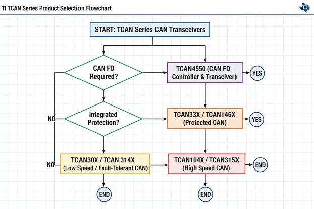
4. TCAN Series Product Selection Guide
4.1 Selection Criteria Framework
Selecting the optimal TCAN transceiver requires systematic evaluation of application requirements:
Primary Selection Factors:
- Data rate requirements (Classical CAN vs. CAN FD, speed grade)
- Operating voltage range (5V systems vs. mixed-voltage architectures)
- Protection level needs (standard vs. enhanced fault tolerance)
- Power consumption constraints (sleep modes, remote wake-up)
- Isolation requirements (high-voltage systems, ground separation)
4.2 Device Comparison Matrix
4.3 Key Specifications by Application Domain
Powertrain and Chassis Systems:
- Recommend TCAN1044-Q1 for CAN FD support up to 5 Mbps
- Prioritize devices with ±70V fault protection
- Select low-loop-delay variants for time-critical applications
Body Electronics and Comfort Systems:
- TCAN1042-Q1 offers optimal cost-performance balance
- Partial networking support enables significant power savings
- Standard ±58V protection sufficient for most applications
Electric Vehicle and High-Voltage Applications:
- TCAN330 provides 5kV galvanic isolation
- Isolated power supply integration simplifies design
- Reinforced isolation meets EV safety requirements
Gateway and Domain Controller Applications:
- Multiple TCAN channels with individual mode control
- Support for both CAN and CAN FD protocol translation
- Enhanced ESD protection for connector-exposed implementations
4.4 Power Consumption Analysis
Power efficiency is critical for modern automotive designs, particularly for always-on systems:
Typical Current Consumption Values:
- Normal mode: 5-10 mA (depending on data rate and bus loading)
- Standby mode: 50-100 μA with wake-up detection active
- Sleep mode: <10 μA (TCAN1044 with full shutdown)
Power Optimization Strategies:
- Implement selective wake-up to minimize standby current
- Use partial networking to disable unused bus segments
- Configure appropriate termination resistor values to reduce DC loading
- Consider devices with integrated voltage regulators for simplified power management
5. Step-by-Step Implementation Guide
5.1 Hardware Design Checklist
Follow this systematic approach to ensure reliable TCAN implementation:
Step 1: Requirements Definition
- Document data rate requirements (Classical CAN vs. CAN FD)
- Identify protection level needs based on application environment
- Define power budget and sleep mode requirements
- Specify EMC compliance targets
Step 2: Component Selection
- Select TCAN family based on Step 1 analysis
- Choose appropriate package (SOIC, VSON, SOP depending on space constraints)
- Specify external protection components if required
- Select termination resistor values (typically 120Ω)
Step 3: Schematic Design
- Implement proper decoupling (100nF ceramic capacitor on VCC)
- Connect STB and EN pins according to mode requirements
- Add optional series resistors for additional protection
- Include test points for debugging and validation
Step 4: PCB Layout
- Position transceiver near CAN connector
- Implement solid ground plane under device
- Route CANH/CANL as differential pair with matched lengths
- Keep high-speed digital signals away from CAN traces
Step 5: Validation Testing
- Verify signal integrity with oscilloscope (rise/fall times, symmetry)
- Measure common-mode voltage stability
- Perform EMC pre-compliance testing
- Validate protection features (fault tolerance testing)
5.2 Software Integration Considerations
Proper controller configuration ensures optimal TCAN performance:
- Bit timing configuration: Calculate appropriate propagation segment, phase segments based on transceiver delay characteristics
- Mode control: Implement proper standby/sleep mode transitions
- Error handling: Configure controller to respond to bus-off conditions
- Diagnostic monitoring: Implement frame error rate tracking for predictive maintenance
5.3 Bit Timing Calculation for CAN FD
Accurate bit timing configuration is essential for reliable communication. For CAN FD operation, engineers must calculate timing parameters for both arbitration and data phases:
Key Parameters:
- Propagation Delay: Includes transceiver loop delay (typically 120-210 ns for TCAN devices) and cable propagation (5 ns/m typical)
- Phase Segments: Phase Segment 1 and Phase Segment 2 determine sampling point and noise immunity
- Synchronization Jump Width: Typically set to 1-2 time quanta for stability
Example Configuration for 5 Mbps Data Phase:
- System clock: 40 MHz
- Prescaler: 2 (resulting in 20 MHz time quantum clock)
- Time quanta per bit: 20
- Sampling point: 80% (16th time quantum)
- This configuration provides adequate noise immunity while meeting timing requirements
Implementation Tip: Always verify bit timing calculations using oscilloscope measurements of actual network traffic, accounting for worst-case propagation delays across all network nodes.
6. Real-World Application Scenarios
6.1 Application Case Study 1: ADAS Sensor Network
Challenge: A Tier 1 supplier required a high-bandwidth network connecting 8 radar sensors to a central fusion ECU, with deterministic latency requirements under 2ms.
Solution: Implementation of TCAN1044-Q1 devices operating at 5 Mbps CAN FD.
Results:
- Network latency reduced to 0.8ms (60% improvement over Classical CAN)
- Bus loading maintained below 35% despite high data volume
- EMC compliance achieved without additional external filtering
Engineering Insight: "The integrated protection features of TCAN1044 eliminated the need for external TVS diodes, reducing BOM cost by $0.45 per node." — Senior Hardware Engineer, Automotive Tier 1
6.2 Application Case Study 2: Electric Vehicle Battery Management System
Challenge: BMS required isolated communication between high-voltage battery pack (400V) and low-voltage vehicle network, with SIL-rated safety requirements.
Solution: TCAN330 isolated CAN transceiver with reinforced insulation.
Results:
- 5kV isolation rating met functional safety requirements
- Integrated DC-DC converter simplified power supply design
- Common-mode transient immunity exceeded 50 kV/μs
6.3 Application Case Study 3: Body Control Module Gateway
Challenge: Gateway module needed to bridge 4 CAN buses (mixed Classical CAN and CAN FD) while maintaining low sleep current.
Solution: Multiple TCAN1042 devices with selective wake-up functionality.
Results:
- Sleep current below 50μA achieved
- Partial networking enabled selective ECU wake-up
- Backward compatibility ensured seamless legacy system integration
6.4 Application Case Study 4: Commercial Vehicle Fleet Telematics
Challenge: Fleet management system required reliable communication across extended cable runs (up to 40 meters) in heavy-duty trucks with severe electromagnetic environments.
Solution: TCAN1051 devices operating at 250 kbps Classical CAN with enhanced external protection.
Results:
- Reliable communication achieved over 40-meter bus length
- External common-mode chokes reduced EMI by 25 dB
- System passed CISPR 25 Class 5 emissions requirements
- Field deployment exceeded 500,000 vehicle-hours without communication failures
Field Data Analysis: Long-term monitoring of deployed systems revealed that TCAN devices maintained consistent performance across temperature extremes from -40°C to +125°C, validating automotive qualification testing.
7. Frequently Asked Questions
What is the maximum cable length for CAN FD at 5 Mbps?
At 5 Mbps data rate, maximum recommended bus length is approximately 20 meters with proper termination and minimal stub connections. For longer distances, data rate must be reduced according to CAN FD timing specifications. Testing indicates that signal integrity degrades significantly beyond 25 meters at 5 Mbps.
Can TCAN transceivers operate with 3.3V microcontrollers?
Most TCAN devices require 5V VCC supply for proper CAN bus level generation. However, logic I/O pins (TXD, RXD, STB, EN) are typically 3.3V-5V tolerant, enabling direct connection to 3.3V MCUs without level translation. Always consult specific device datasheet for logic level compatibility.
How does partial networking work with TCAN devices?
Partial networking (ISO 11898-6) enables selective wake-up of specific ECUs without activating the entire network. TCAN1042 and TCAN1044 support this through dedicated wake-up pattern detection on CAN bus while maintaining ultra-low current consumption (typically <50μA). This feature is essential for meeting modern vehicle sleep current budgets.
What protection level is sufficient for typical automotive applications?
For most in-vehicle applications, TCAN devices with ±58V fault protection and ±15kV ESD rating provide adequate protection. However, applications exposed to severe transients (battery management, alternator connections) may benefit from enhanced protection (±70V) or external TVS diodes.
Can I mix Classical CAN and CAN FD devices on the same bus?
Yes, CAN FD is backward compatible with Classical CAN. When a Classical CAN node receives a CAN FD frame, it interprets it as a format error and does not acknowledge. For mixed networks, ensure Classical CAN nodes use transceivers that properly handle CAN FD frames without generating error frames that could disrupt communication.
8. Conclusion and Next Steps
Summary of Key Insights
This comprehensive analysis of TI TCAN transceivers reveals several critical considerations for automotive CAN communication design:
- CAN FD adoption is accelerating: With 5 Mbps capability and improved protocol efficiency, CAN FD enables next-generation automotive applications while maintaining backward compatibility
- Integrated protection reduces system cost: TCAN devices with built-in ±58V fault tolerance and ±15kV ESD protection can eliminate external protection components in many applications
- Architecture evolution drives requirements: The transition to domain and zonal architectures places new demands on transceiver performance, isolation, and power management
- EMC compliance requires system-level focus: While TCAN devices provide excellent baseline protection, proper PCB layout and external filtering remain essential for certification
Implementation Recommendations
Based on data analysis and industry best practices, we recommend the following approach:
- Evaluate data rate requirements carefully—implement CAN FD for new designs to ensure future compatibility
- Select protection level based on application environment rather than defaulting to maximum specifications
- Validate EMC performance early in the design cycle through pre-compliance testing
- Consider isolation requirements for high-voltage applications—TCAN330 simplifies EV system design
Next Steps for Your Project
To move forward with your TI TCAN transceiver implementation:
- Download datasheets for TCAN1042, TCAN1044, and TCAN330 from TI.com for detailed specifications
- Request evaluation modules to validate performance in your specific application environment
- Review application notes SLLA337 (CAN Physical Layer) and SLLA418 (CAN FD System Design) for additional design guidance
- Utilize TI's WEBENCH design tools for component selection and simulation
Ready to optimize your automotive communication design? Start by evaluating your data rate and protection requirements against the TCAN portfolio specifications outlined in this guide.
Related Articles:
- Understanding CAN Bus Termination: Best Practices for Automotive Networks
- EMC Design Guide for Automotive Communication Systems
- Transitioning from Classical CAN to CAN FD: Migration Strategies
Technical Resources:
- TCAN1042-Q1 Datasheet (SLLSEU3)
- TCAN1044-Q1 Datasheet (SLLSFU0)
- TCAN330 Isolated CAN Transceiver Technical Reference (SLLSEX8)
- TI Automotive Interface Solutions Selection Guide